Introduction
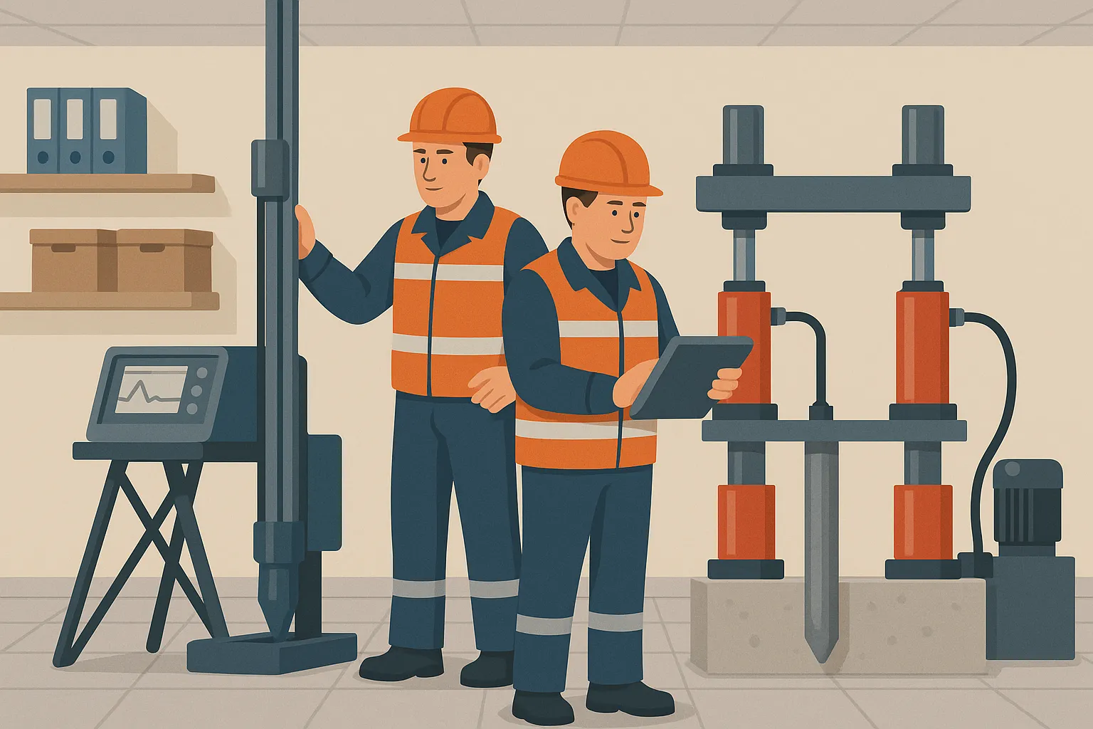
Imagine that you are about to drill a hole in a concrete wall and suddenly you come across a steel bar. This happens if the location of the reinforcement is not determined in advance. Finding reinforcement in concrete is a task that engineers and builders regularly face. In my 11 years of work in the field of non-destructive testing, I have had the opportunity to inspect reinforced concrete structures more than once, and each such project convinces me that knowing where the steel rods are located in a concrete structure is vitally important. Why? Because the safety of work, the safety of the structure and its compliance with design requirements depend on this. In this article, I, an expert engineer, will tell you why searching for reinforcement in concrete is needed and how to do it correctly, I will share professional insights, practical examples and regulatory requirements.
What does concrete hide? In survey practice, it is often found that the actual location of reinforcement differs from the design one. Once, when checking the ceiling, we discovered that the longitudinal reinforcement was displaced 5 cm from the intended position - the carpenters had installed the fasteners incorrectly. If not for timely scanning, the structure could have been drilled in a dangerous place. Finding reinforcement helps you see the invisible, prevent accidents, and ensure that the building is as strong as it was designed to be.
Why look for reinforcement in concrete structures?
There are several reasons why a search for reinforcement is carried out, and all of them are related to the safety and quality of structures:
Avoiding damage during work
Before drilling, cutting or diamond drilling into concrete, it is important to know where the steel bars are to avoid damaging them with the tool. Damaged reinforcement can weaken the structure and lead to costly repairs[1][2]. For example, when installing anchors or laying communications in a wall, knowing the location of the rods helps you choose a safe place for the hole.
Construction quality control
When accepting new buildings or producing reinforced concrete products, they check whether the actual reinforcement corresponds to the design. The correct pitch of the rods, the required number of rods and sufficient thickness of the protective layer - all this is controlled by non-destructive methods to ensure the quality of the reinforced concrete concrete.
Condition assessment and repair of reinforced concrete structures
In old structures, bridges, and foundations, corrosion of reinforcement, cracks, and a decrease in load-bearing capacity are possible over time. Before repairing concrete structures, inspection of the reinforcement helps to understand where the bars lie and what condition they are in, and whether reinforcement is needed. Also, if the drawings are lost, scanning allows you to restore the reinforcement diagram.
Regular construction control
Technical supervision and construction control use the search for reinforcement selectively, checking hidden work. According to requirements SNiP And JV, reinforcement is a hidden work, and before pouring concrete, a report is usually drawn up based on the results of an inspection of the frame. But after concreting, it can only be checked using a non-destructive method.
Scientific and expert surveys
For research purposes, when assessing the strength of structures and determining the remaining service life (for example, to assess the condition of reinforced concrete structures before reconstruction), it is important to know the actual reinforcement: diameter, number of rods, depth.
Practical example: On one bridge that required reinforcement, we scanned the beams and found that the diameter of the reinforcement in some bars did not correspond to the design - instead of 20 mm, we used 18 mm. It would seem that the difference is small, but the cross-sectional area of such a rod is almost 20% less! This is critical for load-bearing capacity:
A = π × d² / 4
and when diameter d decreases from 20 to 18 mm, the area ratio (18/20)² ≈ 0.81 - that is, the reinforcement can withstand 19% less load.
Mathematical justification:
S₁ = π × (d₁/2)² = π × (20/2)² = π × 100 = 314.16 mm²
S₂ = π × (d₂/2)² = π × (18/2)² = π × 81 = 254.47 mm²
Ratio: S₂/S₁ = 254.47/314.16 = 0.81
Where:
- S₁ - cross-sectional area of reinforcement Ø20 mm
- S₂ - cross-sectional area of reinforcement Ø18 mm
- π ≈ 3,1416
This calculation shows the criticality of exact compliance with the design for the diameter of the reinforcement. Having identified this deviation, we made adjustments to the strengthening project. This case illustrates that the search for reinforcement serves not only to “find iron in concrete”, but also to check the quality parameters of the reinforcement.
Basics of concrete reinforcement: why and how reinforcement is laid
To understand how to look for reinforcement, it is useful to understand how it is arranged in a structure:
Purpose of reinforcement
Concrete is very strong in compression, but weak in tension. Reinforcement is steel rods that absorb tensile forces when working in tandem with concrete. Without the steel “filling,” the concrete elements would crack under load[3]. Therefore, rods are placed in beams, slabs, and columns in tensile zones, as well as meshes to absorb temperature and shrinkage deformations.
Types of fittings
Hot-rolled steel of various strength classes is used in construction (for example, A500C is the most common class in the Russian Federation). Rods with a diameter of 10–40 mm usually have a ribbed surface (grooved) for better adhesion to concrete. In old houses you can find smooth reinforcement or even reinforcement with a periodic profile (like the “serpentine” of the 1970s). The diameter of the reinforcement is selected by calculation - the greater the load, the thicker the rod. How to determine the diameter of reinforcement in practice? Below we will look at how to correctly measure the diameter of reinforcement with a caliper and how to evaluate it using non-destructive instruments.
Reinforcement cage
The rods are connected into a spatial frame using tying wire, welding or special clamps. Most often these are longitudinal working rods plus transverse clamps (in beams, columns) or meshes (in slabs, walls). For example, a floor slab can have a grid with a pitch of 200 mm from Ø8 mm reinforcement in two directions.
Protective layer of concrete
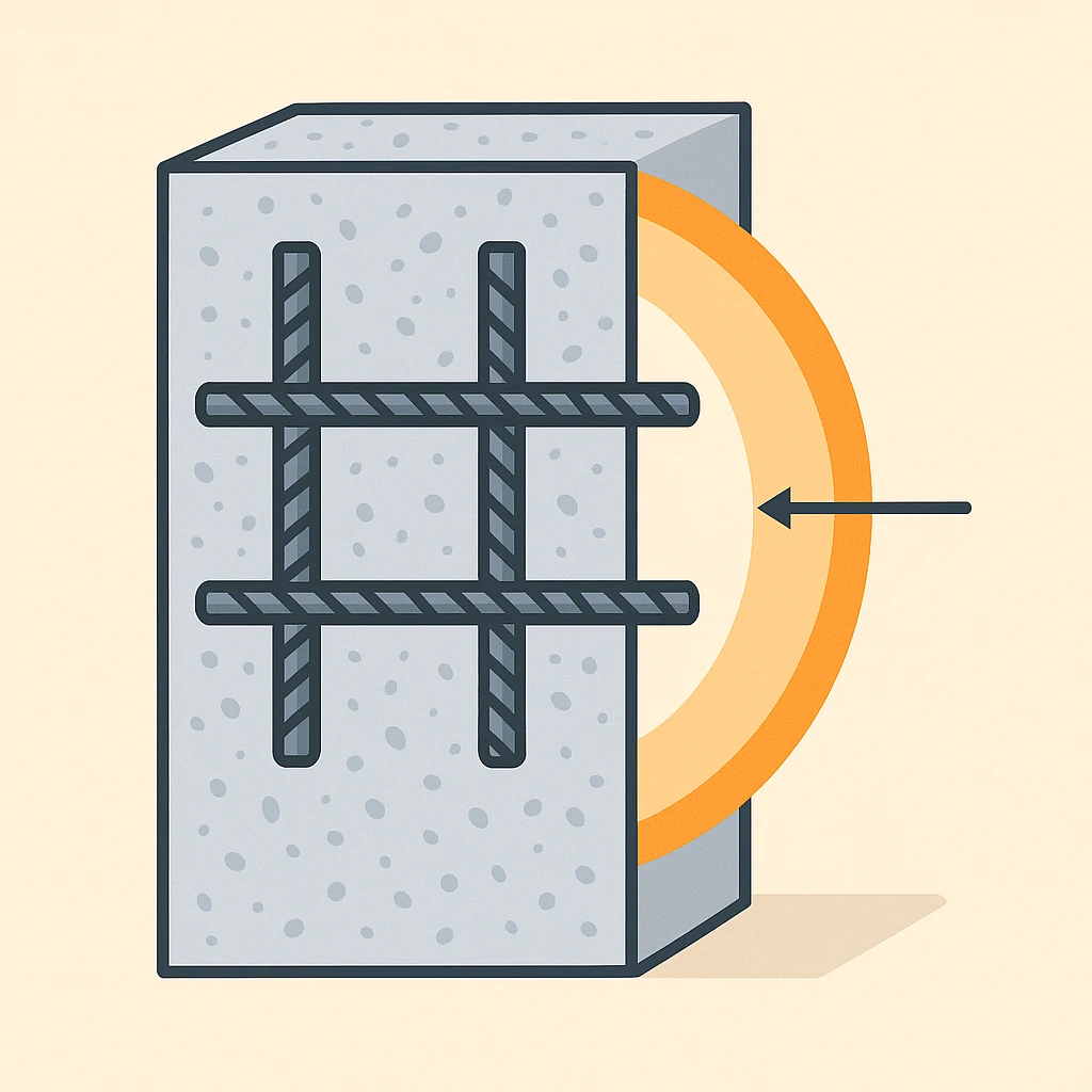
A very important parameter is the distance from the concrete surface to the nearest reinforcement. The thickness of the protective layer of concrete ensures protection of steel rods from corrosion and fire safety. If the layer is too small, the reinforcement will quickly rust or lose strength in a fire; if it is too large, the valve does not work efficiently. The standards establish minimum values: as a rule, no less than the diameter of the rod and no less than a certain value (usually 20–35 mm depending on the design and operating conditions). For example, SP 63.13330.2012 (updated SNiP for concrete and reinforced concrete) requires a protective layer of at least 20 mm for internal elements, 30 mm for external elements, 40–70 mm for foundations. In general, the minimum thickness accepted is: δ_min ≥ max(10 mm, d_rod), and in practice often 20–50 mm.
Formula for calculating the minimum thickness of the protective layer:
δ_min ≥ max(10 mm, d_rod)Practical examples:
- For reinforcement Ø12 mm: δ_min ≥ max(10, 12) = 12 mm
- For reinforcement Ø25 mm: δ_min ≥ max(10, 25) = 25 mm
- For reinforcement Ø8 mm: δ_min ≥ max(10, 8) = 10 mm
Where:
- δ_min — minimum thickness of the protective layer, mm
- d_rod - diameter of the reinforcing bar, mm It is the thickness of the protective layer that is usually checked by instruments when searching for reinforcement.
Terminology Check: The protective layer is a layer of concrete from the surface to the nearest reinforcement. The nominal diameter of the reinforcement is the diameter of a smooth equivalent rod (for corrugated reinforcement, it is better to measure with a caliper along the body, without protruding ribs). Incoming inspection of reinforcement - checking the quality and dimensions of bars at a factory or construction site before use (for example, measuring the actual diameter and tensile testing in accordance with GOST 5781-82 or ISO 6935-2:2019 – standards for reinforcing steel). In our article, the focus is on control already in concrete, i.e. after filling.
Regulatory framework: standards for non-destructive testing of reinforcement
Searching for reinforcement is part of non-destructive testing (NDT) of concrete structures. The following main standards and documents are applied in Russia and the CIS:
GOST 22904-93
GOST 22904-93 “The structures are reinforced concrete. Magnetic method for determining the thickness of the protective layer of concrete and the location of reinforcement.” This standard (reissue 2010, updated in GOST 22904-2023) regulates the use of magnetic and electromagnetic devices for searching for fittings[6]. According to GOST 22904, instruments must determine the location of the reinforcement and measure the thickness of the protective layer above it. Measurement ranges are provided for different rod diameters (for example, for Ø12–32 mm, coverage 10–60 mm) and permissible errors. The error limit when determining the location of the reinforcement is ±10 mm [7], for the thickness of the layer – ±(0.05 t + 0.5) mm (that is, 5% of the thickness, but not less than 0.5 mm) for a single rod [7]. GOST also requires individual calibration of the device for the conditions of a specific structure - using a concrete sample with reinforcement of a known location [8].
GOST 17625-83
GOST 17625-83 “Reinforced concrete structures and products. Radiation method for determining the thickness of the protective layer, the size and location of reinforcement." Standard for the use of X-ray (radiographic) method. Recommends using it for inspecting particularly important structures and during repairs when accurate data is needed[9]. The method uses portable or stationary X-ray machines, gamma flaw detectors, and betatrons[10]. The result is an x-ray image showing the rods and embedded parts inside the concrete. This method is very accurate, allows you to measure the diameter of the reinforcement, the distance between the bars, the presence of defects - but it is expensive, requiring compliance with strict radiation safety standards and qualified personnel.
Other standards
There is no separate GOST specifically about ground penetrating radar (radar method), but it is classified as NK and is used according to general standards (for example, according to the classification GOST 18353-79 ground penetrating radar - NDT method, although this GOST is outdated). There are industry recommendations and foreign standards (for example, BS 1881-204:1988 - British standard for magnetic cover measurement, ACI 228.2R-13 - ACI guide to non-destructive testing of concrete, which describes both reinforcement locators and GPR). In Russian practice, ground penetrating radar is based on a general standard GOST R 56587-2015 (gear radar monitoring of the condition of structures of buildings and structures).
Good to know: If the article mentions a “shut-off valve position monitoring device (VCPZA)”, do not be confused! In Russian, the word “fittings” can mean not only reinforcing steel, but also pipeline fittings (gate valves, gate valves). Our context is precisely construction fittings (reinforcing steel), and not locking devices. Standards for testing pipeline fittings (e.g. GOST 33257-2015 for valves) are not considered here. We are only talking about non-destructive testing of steel bars inside concrete.
Reinforcement search methods: non-destructive testing without damage to concrete
There are several methods of non-destructive search for reinforcement. Let's look at the main ones and compare them to understand which method is appropriate when:
1. Magnetic method (rebar detector)
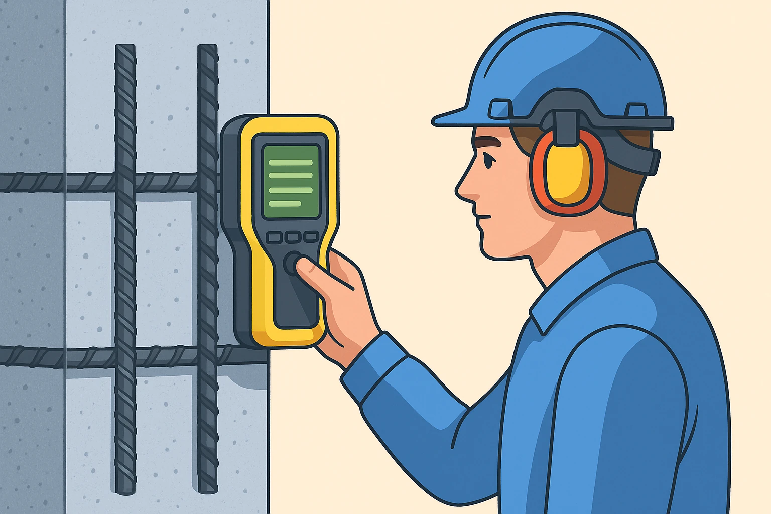
Based on the interaction of ferromagnetic steel with a magnetic field. The instrument (often called a rebar locator, cover meter or concrete rebar detector) generates a magnetic field and detects distortions due to the presence of a steel bar[11]. Modern devices use pulsed electromagnetic induction: current pulses flow in the probe coil, causing eddy currents in the rod, which, in turn, form a response signal [12]. Using these induction effects, the device determines the distance to the reinforcement (thickness of the concrete layer) and is often able to estimate the diameter of the bar. The magnetic method is standardized (GOST 22904). Its advantages: complete indestructibility, simplicity and speed of measurements, compact equipment. Among the limitations: it is mainly suitable for carbon steel (it will not see aluminum or composite rods), sensitive to closely spaced rods (if the rods are very dense, the signals overlap). Calibration for a specific diameter is also required: the device measures the protective layer more accurately if the nominal diameter of the reinforcement is known.
2. Electromagnetic eddy current method
In fact, this is a type of magnetic, sometimes isolated separately. The principle is similar: inducing eddy currents in the metal and measuring the response signal. Eddy current instruments are usually used for surface detection of defects, but they are rarely used for reinforcement in concrete, because the reinforcement is covered with a layer of concrete, and classic eddy current sensors sense at shallow depths. Therefore, they often talk about the magnetic method as a whole (including both a constant field and an alternating one).
3. Metal detector method
In fact, household metal detectors are also electromagnetic devices that work by changing the inductance of a coil near the metal. The simplest rebar detector can be a hand-held metal detector. However, professional devices are tuned specifically to ferromagnetic metal (steel) and are calibrated to estimate depth. A metal detector can distinguish between ferromagnetic and non-ferromagnetic objects[13], but will not provide accurate information about the diameter or spacing of the rods. It is mainly used for preliminary search - “is there metal or not.” If the reinforcement is deep (>10–15 cm) or very thin, simple detectors may not notice it.
4. Radar method (ground penetrating radar, GPR)
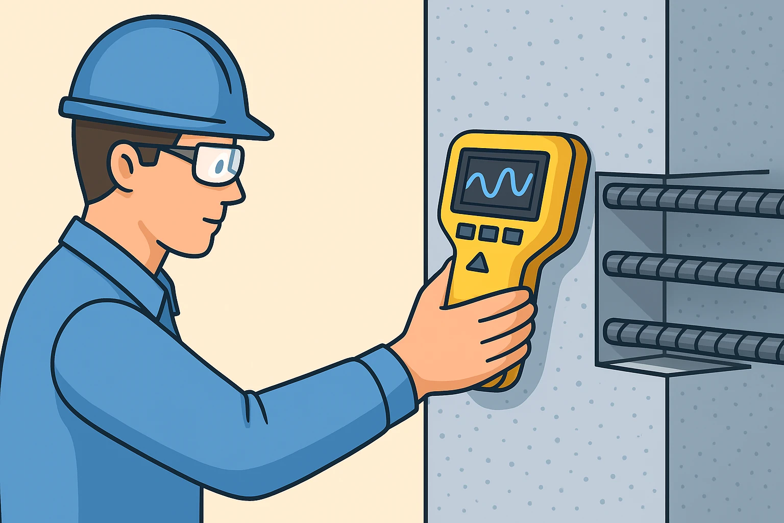
GPR (Ground Penetrating Radar) emits ultra-high frequency electromagnetic waves into concrete, which penetrate inside and are reflected from interfaces - from objects with other electrophysical properties. Steel reinforcement has high electrical conductivity, strongly reflects the signal and causes noticeable anomalies. The result of the scan is a radargram in which the reinforcing bars appear as characteristic hyperbolic reflections[14]. Based on the shape and intensity of these signals, a specialist determines the depth of the reinforcement, the pitch, possibly the diameter, and also sees other inhomogeneities: voids, cracks, plastic pipes, cables, etc.[15]. Advantages of GPR: large penetration depth (up to tens of centimeters, and at low frequencies up to meters - you can scan thick foundations, bridge supports), the ability to cover a large area and get a picture of the distribution of reinforcement over the entire area, rather than point measurements. Modern devices make it possible to create a 3D model of a reinforcement frame using a set of radargrams, with visualization of each rod. For example, the Proceq GP8800 scanner is capable of generating a real-time image of the location of bars on the tablet screen. Disadvantages: high cost of equipment, the need for an experienced operator to interpret the data, reduced resolution with very dense reinforcement (when reflections can merge). Also, wet concrete or the presence of salts can shield the radio signal, reducing the scanning depth.
5. Radiographic method (X-ray)
The most informative, but also the most difficult method. An X-ray apparatus (or a gamma flaw detector with an isotope, for example Ir-192) is installed on one side of the structure, and on the other is photographic film or a digital receiver. When transilluminated, the film displays dark silhouettes of reinforcement, voids, and defects. An X-ray image gives a direct image: you can measure the diameter of the reinforcement in the image, determine the exact distance between the bars, and see the presence of cracks in the concrete (as a weakening of the density). This method is used when high accuracy is needed and there are no other methods - for example, in thick structures where a magnetic locator or ground penetrating radar cannot “finish off”, or in critical objects (bridges, dams) for careful monitoring. Because of the danger and high cost, radiography is used in a targeted manner. According to GOST 17625-83, the radiation method is indicated for the examination of especially critical structures during operation and repair [9]. It is necessary to fence off the area and only allow certified personnel with dosimeters to work. As a result, the customer receives an x-ray and a report from a flaw detector.
6. Ultrasonic method
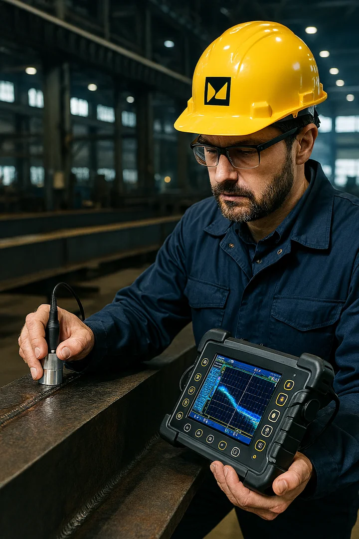
Direct use for searching for reinforcement is limited, but we will mention it. Ultrasonic devices (for example, type A1040 MIRA tomographs) pass elastic waves through concrete. In principle, they can detect large steel inclusions as areas of very different acoustic impedance. But ultrasound is more suitable for assessing the strength of concrete and identifying defects (cracks, delaminations). I use an ultrasonic tomograph when I need, for example, to find a zone of lack of penetration or determine the depth of a crack in concrete - reinforcement is also visible on the echogram, but searching for reinforcement with ultrasound is a side function. Therefore, if the goal is to find and measure reinforcing bars, a magnetic or radar method is usually chosen.
Which method should you choose? The choice of method depends on the tasks and conditions:
- Need to quickly check a large building for compliance with the design? Magnetic rebar locators do an excellent job of selectively monitoring the protective layer and diameter. They are mobile and simple.
- Do you need to make a reinforcement map for a 20x20 m slab for strengthening? A georadar-based reinforcement scanner in concrete will help here - it will show the location of dozens of bars at once and identify possible hidden voids.
- Extra thick construction or extra precision? For example, a 1-meter wall - here you may need fluoroscopy: a couple of pictures will give complete information, although this is expensive.
- Common situation - drilling holes? A regular rebar detector in the wall is enough to simply localize the rod and not damage it. Even amateurs have these (household detectors are often combined: they detect wires, fittings, wood beams).
In practice, a combination of methods is often used. For example, when inspecting a bridge: first, a large surface of the span slab is scanned with a ground penetrating radar, then individual sections are clarified with a magnetic device (it more accurately measures the thickness of the layer), and in case of controversial issues, control drilling is done with a thin drill for verification - the so-called control opening (mini-destruction, which is then repaired). It is important that all non-destructive methods do not affect the load-bearing capacity - we scan rather than drill load-bearing reinforcement. This is a key advantage of NK.
Devices for searching for reinforcement in concrete: detectors, locators, scanners
Now let’s look at the devices themselves that are used to search for reinforcement. There are many models on the market - from simple to high-precision. Let's look at their characteristics and capabilities.
Detector of reinforcement in concrete (magnetic locator)
The classic device for searching for reinforcement is a magnetic locator. It can also be called a protective layer meter, reinforcement detector, reinforcement scope. Examples: domestic IZS-T (IZS series device), Swiss Profometer, Russian NOVOTEST Armaturoscope, Chinese analogues (for example, ZBL 700).
What does he look like? Usually this is a compact device with a sensor (coil) and an electronic unit with a screen. The operator moves the sensor over the concrete surface. The device signals (sound, light, numbers on the screen) when a rod is detected. The simplest models show only the fact of the presence of reinforcement and the approximate distance to it (indicated by a scale). More advanced ones allow you to switch the mode and, knowing the distance, estimate the diameter of the reinforcement by the change in the signal. For example, Profometer PM-600 automatically calculates the diameter, if the protective layer is not too large, with an accuracy of ±1 size (that is, it will distinguish No. 16 from No. 18)[16][17].
Measurement accuracy. Modern locators are very accurate in measuring the thickness of the protective layer: an error of 1–2 mm with typical thicknesses up to 50 mm[7]. But with large thicknesses (for example, a layer of 100 mm), the error increases. The diameter is determined with an error of the order of ±1–2 mm, provided that the rod is single and the calibration is carried out correctly. The rebar locator is capable of detecting a bar at a depth of up to ~180 mm in the best case (Profometer, Elcometer) [18], but realistically, to confidently determine the diameter – up to ~80–120 mm. If the reinforcement lies deeper, the signal weakens, although the very fact of the presence of metal can be detected by the device (without exact parameters).
Device example: MIT ARMOTRACK – domestic line of devices. The Armotrek 2-1 rebar scanner, for example, has a cover measurement range of 5–210 mm and automatically builds a 3D model of the reinforcement cage on the display. Below is a small comparative table of characteristics of two models in this line:
Table 1. Comparison of characteristics of MIT ARMOTRACK reinforcement detectors
| Characteristic | MIT ARMOTRACK 1‑1 | MIT ARMOTRACK 2‑1 |
|---|---|---|
| Range of Ø measured fittings, mm | 2 – 50 | 6 – 50 |
| Thickness of the protective layer, mm | 1 – 200 (up to 300 with additional sensor) | 1 – 120 / 5 – 210 |
| Additional features | Auto-determination of reinforcement direction; USB/Bluetooth export; IP54 protection | 3D model of the frame; laser marking; telescopic extension; data synchronization; Bluetooth on PC |
| Results memory | 10,000 measurements | 2,500 components (reinforcement elements) |
| Measuring accuracy Ø, mm | ±1 (for Ø 6–32) | ±1 (specific) |
| Accuracy of protective layer, mm | ±1 (≤60 mm) / ±2 (60–200 mm) | ±1 (1–80 mm) / ±2 (81–120 mm) / ±4 (121–210 mm) |
| Screen | LCD with backlight | 2.8″ color touchscreen + extra. 1.3″ display |
| Nutrition | 4×AA or battery (~20 hours of operation) | Li-ion battery (up to 16 hours), removable |
Note: It can be seen that the more advanced model 2-1 has advanced functions (3D scanning, laser marking on the surface for ease of binding, data transfer to the cloud). In practice, when choosing a rebar detector, you should pay attention to the depth of the rebar search, the supported range of diameters and the convenience of the interface. For example, Rebar scanner MIT ARMOTRACK 2-1 is able not only to find rods, but also to visualize their distribution, which is very useful during examinations.
Life hack from experience: How to correctly measure the diameter of reinforcement with a caliper? If you have a rod end exit or sample, you need to measure without taking into account the corrugations. Those. slightly rotate the caliper so that its jaws touch the body of the rod, and not the tops of the ribs - in fact, measure the diameter “along the body”. For corrugated fittings, it is correct to measure this way, otherwise you will get an overestimated value. You can also measure the circumference with a tape measure: grab the rod and divide the length by π - this will give the average diameter. For example, if the tape measure shows 63 mm, then the diameter is approximately 63/π ≈ 20.05 mm, which corresponds to Ø20 fittings.
Formula for calculating the perimeter diameter:
d = P/πPractical calculation:
d = 63/3.1416 ≈ 20.05 mmWhere:
- d—diameter of reinforcing bar, mm
- P—rod perimeter, mm
- π ≈ 3,1416
This method is especially useful when the end of the rod is difficult to grasp with a caliper. This method is convenient when the end of the rod is difficult to grasp with a caliper (for example, a short outlet from a column).
Scanner for reinforcement in concrete (ground penetrating radar and other systems)
Scanners are often called devices with advanced scanning capabilities of concrete structures. This includes ground penetrating radar and combined systems. For example, the Hilti PS1000 X-Scan is a portable scanner that combines a radar unit and visualization software that allows you to see an image of reinforcement on the screen in the field. There is the concept of a subsurface structure scanner - this is essentially the same ground penetrating radar, adapted for concrete.
Scanner features:
- They are often larger than hand-held locators and can be moved on wheels or carts along the surface. Immediately cover a strip with a width of, for example, 600 mm.
- They give a picture of the distribution of reinforcement. For example, a grid of bars will appear as a grid of dots/lines on the screen.
- The scanning depth of professional georadars for concrete is up to ~0.5 m (500 mm) for large objects. But at the same time, the radar may show smaller reinforcement at extreme depths worse (resolution decreases).
- Identification of inhomogeneities. In addition to the bars themselves, the scanner detects voids, for example, unfilled concrete (“sinks”) or channels. On the radargram, defects differ in appearance from reinforcement[14]. An experienced interpreter can distinguish from the shape of the hyperbolas what exactly is inside: a rod (metal, strong reflectivity) gives a clear hyperbola, emptiness gives a weak reflection and almost does not dampen the signal[19].
- Some scanners combine magnetic and radar techniques to compensate for the disadvantages of each. They may also have a built-in metal detector for rough searching.
- Data processing usually takes place on a computer: specialized software allows you to build sections and 3D images. The specialist processes the radargram - an important stage that requires skills (you need to filter out interference, select the speed of wave propagation in a given concrete, etc.).
Well-known scanners include: Proceq GPR Live, Sensors & Software Conquest 100, GSSI StructureScan. Russian companies also offer complexes, for example, Betonoscope from ARADS - essentially a georadar with reference to a coordinate grid (they use a mat with QR marks to track the position of the scanner)[20]. This approach provides high positioning accuracy, suitable for drawing reinforcement schemes. In my experience, the use of GPR pays off on large objects: once, when inspecting an industrial floor of 30x30 m, we mapped the location of all the reinforcement mesh and technological voids in a day, whereas with a point magnetic locator it would have taken weeks.
Radiographic testing equipment
Separately, it is worth mentioning equipment for x-ray inspection of fittings. These are portable flaw detectors or the RPD-200 gamma flaw detector. Typically, the kit includes: the emitter itself (an X-ray generator or a container with a radioactive source), receivers (radio film or digital detectors), tripods, protective screens, and a remote control. Modern digital systems allow you to immediately view images on a laptop, but are very expensive. Therefore, the old method is often used - film: exposed, then developed chemically, as in medicine.
Application: radiography in concrete structures is the domain of special laboratories. For example, when inspecting bridges for cracks in beams, gamma flaw detection can be used. But, of course, they don’t use it en masse – it takes a long time and is dangerous.
There was a case in the author’s practice: it was necessary to find out whether two reinforcement bars were connected by butt welding inside a column. No non-destructive method has shown this directly. As a result, they took an X-ray of the problem unit - and on the film they saw a characteristic overlap and the absence of a joint (that is, the rods were not welded, but simply overlapped and filled with concrete). This saved the column from overload, identified defects and further strengthened the element.
Safety precautions: Working with X-rays requires compliance with radiation safety standards. Personnel must have NDT certificates for the radiation method, constantly monitor the radiation level with a dosimeter, and set up barriers. Sometimes the sanitary and epidemiological service is involved during field trips. Therefore, if you have a small private task (for example, finding reinforcement in the wall of a house), the X-ray method is not an option - it is better to use a locator or ground penetrating radar.
Related Tools
In addition to the main instruments, the survey specialist can use other tools:
Calipers and templates
To quickly measure the visible part of the reinforcement (for example, outlets or meshes on the surface). Often laboratories have plastic templates with cutouts for different diameters - if you attach them to a rod, you can immediately see whether it is 14 mm or 16.
Endoscopes and video borescopes
Thin cameras that are inserted into drill holes. They can be used to look at the fittings inside (to determine the condition, the presence of corrosion).
Chemical indicators
For example, a spray to detect corrosion of reinforcement or the depth of carbonation of concrete (phenolphthalein indicator). They don't look for rebar, but provide context on its condition.
Hammer and sclerometer
Indirectly, by tapping, you can sometimes determine the location of large rods (the sound is louder above the reinforcement). But this is more of an old rule of thumb. It is much more effective to use a modern sclerometer to assess the strength of concrete - by the way, about methods of testing concrete for strength can be read in our blog article – non-destructive approaches are also important there.
Examination technology: how to do it right
When a method and device are chosen, it is important to carry out the measurements correctly. Let us describe the general procedure for carrying out work when searching for reinforcement.
Preparation for work
1. Study of the object and documentation
Before the inspection, the engineer studies the drawings (if any) - this gives an idea of where the reinforcement should be approximately, what diameter, and with what spacing. If there are no drawings, they evaluate it constructively: for example, in a typical slab there are usually two grids, upper and lower, in a beam there are several rods at the bottom, several at the top, connected with clamps.
2. Visual inspection
The concrete surface must be accessible. Peeling plaster and paint layers are removed, if possible, in the measurement areas, and dirt is cleaned. If the concrete is rough, this does not interfere with a magnetic device, but an ultrasonic tomograph requires a relatively smooth surface (sometimes it is necessary to grind the spot).
3. Marking the measurement grid
In practice, it is useful to draw a grid on the surface being examined (for example, in steps of 20 cm) and coordinate axes with chalk or a marker. This makes it easier to navigate and record results. Plus, you can mark the found rods directly on the concrete with dots or lines. In the final report, they often provide a diagram on which the rods are marked - so it’s convenient to draw it with markings.
4. Instrument calibration
A very important moment. According to GOST 22904, individual calibration is performed on a fragment of the structure or a special sample[8]. At a minimum, the device must be calibrated “in air” (zero mark) and on reference plates (usually metal plates or known thicknesses of the protective layer are included in the kit). Many electronic locators have an automatic calibration mode - it is worth starting it before use. The nominal diameter (if known) is also entered - the device will build on this to calculate the thickness. For example, we set the diameter to 16 mm, and the device is calibrated to the signal-thickness curve for Ø16. In georadar, it is important to set the speed of propagation of the electromagnetic wave in concrete - usually ~0.1 m/ns for dry concrete, but it is adjusted for moisture. A properly configured device is the key to accurate results.
Advice: test the device on a known object. I always start by looking for the accessible end of the reinforcement (for example, the outlet from the slab at the junction with the column) and point the sensor at it - the device should show the minimum protective layer (almost 0) and correctly determine the diameter. If something is clearly wrong, it is better to reconfigure or check the batteries 😊.
Taking measurements
1. Search for reinforcement by scanning
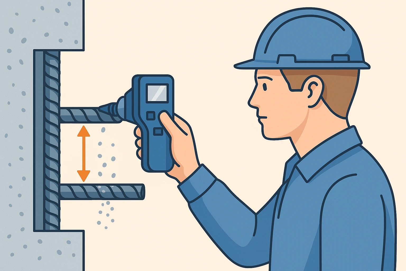
Move the sensor smoothly across the surface. Magnetic detectors usually give an audible signal when the center of the coil is exactly above the rod - a characteristic peak. To accurately mark the position, you can draw a cross on both sides and mark the intersection point. The Profoscope type locator of reinforcement in concrete has a visualization mode: a diagram of the bar is displayed on the screen - this is convenient, you can immediately see when you are above the bar. The GPR is usually moved evenly along the profile; the reinforcement signal appears as a hyperbola on the screen, the operator marks its top - this is the projection of the rod onto the route. Modern radars can also send a signal when an object is found, but more often the analysis occurs after the passage.
2. Measurement of the protective layer
When the rod is found, we fix the device directly above it and read the thickness of the protective layer - this is the main measurement. For example: “reinforcement detected, protective layer 25 mm.” If the device supports automatic mode, it immediately writes this value into memory.
3. Diameter determination
In magnetic instruments, it is often necessary to perform two measurements on one rod: first, the protective layer is measured at an assumed diameter (for example, 16 mm), then the device asks to move the sensor until a weak signal is received at the edge of sensitivity. Based on the signal change, it will calculate the diameter. In advanced models such as Profometer PM-630, you can move the sensor across the rod - the resulting induction curve is compared with the reference ones, and this is how the Ø is determined. How to measure the diameter of the fittings accurately? If you have access, it is better to use a caliper, as described above. But it is not always possible to open the concrete. Therefore, the instrumental assessment gives an idea of the number: let's say, you understand that there is either Ø12 or Ø14 - and you can already check the project that was laid down. An error of 1–2 mm usually does not interfere with the conclusions.
4. Repeat on a grid
We will systematically inspect the entire required area. For example, a customer wants to know the distance between reinforcement. To do this, just find each bar and mark it. Then measure the distance between the marks with a tape measure - we get the step. If some rods are deeper (double-layer reinforcement), the magnetic locator may show the near row, but not the far one. In this case, we resort to georadar or partial opening. Sometimes selective scanning is used: first, a powerful magnet is used to find the upper mesh, then a small fragment of concrete (lacuna) is carefully cut off in the gap between the upper bars - and the sensor is “translated” below, catching the second row. But this is already a semi-destructive method and is done only when absolutely necessary and with the consent of the customer.
Typical measurement problems and how to solve them:
- Closely located fittings: if the pitch of the rods is less than the minimum distance of the device, the signals are merged. GOST 22904 indicates that with cross reinforcement with a pitch of less than 100–150 mm, the error increases [21]. Solution: use a smaller sensor (point probe), scan at an angle, or use a radar that sees separately in depth.
- Design edges: near the edge (corner) the magnetic device may “lose” calibration, because the field line goes out. It is best to calibrate away from the edges and allow for the possibility of ±5 mm error at the edges.
- Influence of external magnetic fields: for example, a substation nearby or large metal objects. Usually this is not critical, but highly magnetized objects can emit radiation. It is necessary to exclude the presence on the surface of, say, a reinforcing mesh on which the operator walks 😊 - there were cases when the device reacted to the iron heels of the engineer’s boots.
- Human factor: The most common mistake is incorrectly recorded results. With a large volume, it is easy to confuse the labels. Therefore, it is important to methodically number points, keep a log, or use the device’s memory. My reports always have a table of measurements: point number, layer, diameter, notes.
Processing of results and registration
After field work comes the stage of analysis and design:
Summary of data
If you used an electronic device, upload the data to your computer (via USB, Bluetooth). Specialized programs (for example, Proceq Profometer Link or Armotrek software) build graphs of the distribution of the protective layer and statistics. If you wrote it manually, we enter it into an Excel table.
Construction of reinforcement schemes
Based on the marks on the structure, a drawing or sketch is drawn up. Typically, a grid of beams, columns, or slabs is drawn and the location of the detected bars is plotted. A distinction is made between upper and lower reinforcement (if the depth is known, you can understand that the upper mesh of the slab is usually ~20–30 mm from the surface, the lower one is closer to the bottom edge).
Compliance assessment
Based on measurements of the thickness of the protective layer, it is concluded whether they correspond to the required ones. For example, if according to SP there is a minimum of 25 mm, and we found places with 15 mm, it is indicated as a deviation that requires elimination (for example, with a protection device or repair). Also a comparison of the actual diameter and the design one: “The design provides for reinforcement Ø16 mm, according to the NDT results in the design – Ø12...14 mm. This is a discrepancy with the requirements of the project, a reduction in the cross-section of ~30%.”
Report and recommendations
The official conclusion usually includes: a description of the object, methods (with references to GOSTs, what instruments were used, with what errors), results (in the form of tables and diagrams), photographs of the work site, conclusions and recommendations. For example: “It is recommended to strengthen beam No. 3, since the absence of two rods with a diameter of 20 mm in the span was discovered - the reinforcement is below the standard.” Or: “The thickness of the protective layer in the columns meets the requirements (30–35 mm in fact, compared to the norm of 30 mm); no local zones with unacceptable exposure of reinforcement have been identified.”
The question is often asked about the cost of the examination. Of course, prices are not written in the report, but customers care about this. The price depends on the technique: the cost of examining reinforced concrete structures using the magnetic method is usually calculated by the number of points (for example, 100 rubles/measuring point). Georadar - by area (say, 100 rubles/m²). X-ray - according to the number of images (maybe 5,000 rubles for 1 image or changing the operation of the device). Specific numbers vary regionally. But as an expert, I will say: you cannot skimp on control, because the price of a mistake is safety. How much more will it cost? repair of concrete and reinforced concrete structures, if something goes wrong due to an unknown reinforcement pattern.
Practical cases of application of the method
Let's consider where in practice the search for reinforcement is most often used and what mistakes can be avoided thanks to it.
Inspection of reinforced concrete structures of buildings
During comprehensive technical inspections of buildings (before reconstruction, in case of suspected defects), searching for reinforcement is a mandatory item. Inspection engineers check the type of reinforcement, pitch, diameter, and quality of concrete. For example, in panel houses from the 1970s and 80s, you need to make sure that the panel joints are properly reinforced. In monolithic frames - that columns and crossbars have rods laid down by the design. There was a case when, while examining an industrial frame, we discovered missing rods in the floor slab - they simply forgot to lay them during concreting! The locator showed large areas without response where the reinforcing mesh should be. As a result, the building was further strengthened, but it’s good that they checked it before putting it into operation.
Another example is assessing the condition of concrete in an aggressive environment. Columns at a chemical plant were experiencing corrosion. We looked for reinforcement and measured its depth. Where the protective layer was less than 5 mm (in some places the reinforcement was practically exposed), severe corrosion of the rods was indeed observed. Based on the results, a map was drawn up: critical zones where the layer was < 10 mm were marked, they were milled out and re-coated with a repair compound. Regular monitoring of such structures (for example, every 5 years) allows you to plan the restoration of reinforced concrete structures in time - not to wait for an accident, but to carry out preventive repairs.
Repair of concrete structures and strengthening
When repairing reinforced concrete structures (cracks, reinforcement with plates or jackets), they must be scanned for the location of the reinforcement. Why? For example, if you decide to enclose a column with a clip, you need to know where to drill holes for the anchors so as not to get into the longitudinal reinforcement. Or when injecting cracks, it is important not to drill through the rod, this will reduce its cross-section. We usually help reinforcement designers: we mark the column reinforcement grid with a marker on site, and then the installers fasten the steel sheets between these marks.
These technologies are also used when repairing bridges. Repair of concrete and reinforced concrete bridge structures often involves strengthening roadway slabs and replacing sections of beams. Before this, all spans are inspected with ground penetrating radar - this is how areas of possible corrosion are identified (in places of leaks, for example, the reinforcement may “bounce back” less easily, since the cross-section has decreased). They also look for voids under the concrete (delaminations) - the radar sees them well. Then, during repairs, the picture is known: where concrete replacement is needed, where sealing cracks is sufficient.
In the process of repairing reinforced concrete structures, diamond drilling of holes or cutting of openings is sometimes required. Here you cannot do without a detector, otherwise the saw blade can cut many rods, weakening the element. In one parking lot, when constructing a new opening, workers neglected to scan - as a result, they cut 4 reinforcements in the slab, and the slab cracked. I had to quickly strengthen it and spend a long time figuring out who was to blame. Now almost all responsible contractors have a simple detector in their team - it pays off.
Quality control at concrete factories
At factories of reinforced concrete products, incoming inspection of reinforcement is often used (for example, they check whether the bars correspond to the diameter markings and whether they are even). But even after the manufacture of panels or beams, control of reinforcement is also relevant. Factories can use protective layer thickness gauges to check whether the meshes are installed correctly in the product - this is part of the acceptance quality control. For example, GOST 13015 (for reinforced concrete products) requires checking the thickness of the protective layer for 5% of the products in the batch. Using a magnetic device allows you to do this quickly without destroying the panel.
Also, some products, such as floor slabs, have a certain distribution of reinforcement in the project. If something went wrong (displacement of the frame during pouring), the control sample will immediately reveal it. In my practice, there was a case at a factory when the vibration of the machine shifted the bottom grid of the slab down 1 cm - the device showed a layer of 5 mm instead of 15 mm. The products were rejected (too small a layer does not guarantee adhesion and anti-corrosion protection), and the process was set up again.
Thus, the search for reinforcement also serves to control the quality of concrete products directly upon release - this is an important element of the quality assurance system.
Survey of bridges and infrastructure
We would like to specifically mention the inspection of bridges. The stakes here are high: people’s lives depend on the reliability of the reinforcement, because the destruction of a bridge is a disaster. Bridge structures (spans, supports) are traditionally regularly inspected (the norm is complete inspections at least once every 5 years). Reinforcement search is used:
- To check for corrosion: measure the protective layer and determine whether it is sufficient and whether there is any exposure. Also, by indirect signs - rusty spots, radar images - areas of rod corrosion are identified.
- To control deformations: if the bridge was overloaded, cracks and openings could occur, sometimes leading to displacement of the reinforcement. A scan will detect if the rod is severely bent or burst (but the latter is more likely to be done with an x-ray or endoscope).
- To upgrade: when expanding a bridge or strengthening purlins, you need to know the layout of the old reinforcement. Often, for old bridges, the drawings are lost or do not correspond to the facts (especially if the bridge is pre-war or has a complex history). Then they scan the spans with ground penetrating radar and build a map of all the reinforcing bars. By the way, GPR is convenient for large, extended objects; it can be mounted on a trolley and quickly driven along the beam, obtaining a picture along the entire length.
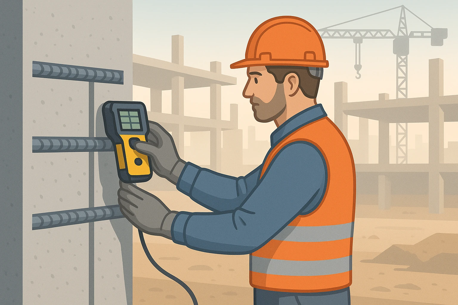
Example: When assessing a reinforced concrete overpass from the 1980s, we used ground penetrating radar to find places where reinforcement was missing over a significant area. It turned out that during construction, technological holes were filled in, but the reinforcement around was not strengthened - a zone without rods was formed. In the strengthening project, this was taken into account and steel linings were added. Without searching for reinforcement, this “Achilles heel” of the structure could have been missed.
Construction control and technical supervision
During ongoing construction control on site, technical supervision also uses devices. For example, checking the protective layer in columns immediately after removing the formwork is common. Many construction companies are now equipped with inexpensive thickness gauges, and foremen themselves run through the columns, noting: “so, here the concrete covers the reinforcement by only 1 cm - it needs to be greased.” Because they know: technical supervision will come and measure it too, and issue an order.
Also, the incoming control of reinforcement (as a material) was mentioned - in a warehouse they can “shoot” bars with a manual device like ARMCOR-1 - this is a corrosion analyzer, it measures potential and resistance, assessing the risk of corrosion of reinforcement inside concrete [22], but it can also work simply on bars.
In the field of road construction, when constructing tunnels and overpasses, control of reinforcement is important for quality and safety. Laboratory testing of concrete (cubes for strength, etc.) is one thing, but if the reinforcement is mixed up or displaced, the strength of the entire structure is at risk. Therefore, competent technical supervision must include the item: “monitoring of reinforcement works using non-destructive methods.”
In the era of digitalization, new opportunities are also emerging: companies are introducing BIM models with information about reinforcement, and scanning results can be immediately entered into a digital twin of the building. The future lies in the fact that any deviation will be immediately visible: you compare the BIM project (ideally) and the data cloud from the scanner - and you see where what is missing.
Answers to frequently asked questions (FAQ)
Question 1: How to correctly measure the diameter of reinforcement with a caliper?
Answer: If the reinforcement is grooved, you need to measure along the body, and not along the protrusions. Open the jaws of the caliper and place the rod so that the jaws rest against the base of the edges (protrusions). Or take a micrometer - its heels better fit the profile. The correctly measured diameter is the diameter of a conventional smooth rod of the same cross-section. You can also use the formula through a circle: measure the circumference with a tape measure L and calculate d = L/π. Vernier calipers are often used to measure at a construction site, when the reinforcement sticks out of the concrete, or in a warehouse - this is how they check compliance with the markings (for example, an 18 mm brand rod should have ~18 mm, the tolerance is small). Remember that large-diameter bars may have corrugations up to 2 mm high, so direct measurement over the ribs will give an overestimation. How to measure corrugated rebar diameter correctly? – Clean off beads and rust, turn at an angle to get between the ribs, and gently squeeze the caliper until it touches. Then the figure will be close to the nominal value.
Question 2: Is it possible to find reinforcement in a concrete wall with a household detector from a store?
Answer: Partially yes. There are inexpensive hand-held detectors for fittings in the wall, often they are also wiring detectors (Bosch, Condtrol, etc.). They work on the principle of changing the electromagnetic field. Such a device can show where the bar passes, usually with an audible or LED signal. But the accuracy and depth are limited: as a rule, it will detect Ø12 up to 50–70 mm in depth, but not at 150 mm. And it won't give you numbers (layer thickness or diameter). Therefore, it is suitable for domestic use - to hang a shelf and not get caught in the fittings. For important surveys, you need professional instruments for determining reinforcement in concrete with calibration and passports. By the way, the price of professional ones is from 1000 USD and above, while household ones can be bought for 50–100 USD. The difference is that a professional device guarantees an error, is recorded according to GOST, and the results are legally significant.
Question 3: What is more important to control – the protective layer or the diameter of the reinforcement?
Answer: Both are important, but in the context of non-destructive testing it is more common to control the thickness of the concrete cover layer. This is a critical parameter for the durability of the structure. Projects always contain requirements for a protective layer (for example, “protective layer class X0 - at least 20 mm”). And the devices allow you to effectively and accurately check this throughout the entire structure. The diameter of the reinforcement is usually known from the design, and changing it is a rare violation (but it does happen!). If there is a suspicion that they installed rods of a smaller diameter (for example, according to the marking they say 18, but in reality it is 16), then they check it, sometimes even destroying it (drill out a piece and measure it accurately). Non-destructively, the diameter is determined with some error - this is enough to sound the alarm, but for an act of non-compliance they may ask for an autopsy and direct measurement. In general, monitoring the position of the reinforcement and the thickness of the protective layer is a minimum NDT program, and estimating the diameter depends on the situation.
Question 4: How often should valves be inspected in an operating structure?
Answer: The regularity depends on the purpose of the structure and its condition. For ordinary buildings without signs of problems, there is often no need to specifically look for reinforcement. This is done during a general technical inspection every 10–15 years. For bridges and overpasses - approximately every 5 years, as part of a comprehensive inspection. If the structure is exposed to aggressive influences (chemically active environment, maritime climate), it makes sense to monitor more often. For example, parking lots where deicing agents are used: salt penetrates the concrete and accelerates corrosion of the reinforcement. There you can check the protective layer and the potential corrosion state of the reinforcement once every 5 years (there are devices that evaluate corrosion by the electrochemical potential of steel reinforcement). Technical supervision usually inspects the building visually annually, but if rust spots, cracks with corrosion are noticed, then an unscheduled detailed NDT is prescribed, including a search for reinforcement. Bottom line: for critical objects - regularly according to schedule, for others - as needed (during reconstruction, when defects are detected, after emergency impacts).
Question 5: Is it possible to buy one universal device for everything?
Answer: There are integrated rebar detectors on the market that combine different methods. For example, scanners are produced that simultaneously use both magnetic and radar channels for maximum reliability. However, they are expensive and quite complex. Usually, each device is “tailored” to its own: magnetic – the layer/diameter is better in accuracy, radar – it sees deeper and wider. If the budget is limited and the tasks are not too complex, I would recommend purchasing a professional reinforcement thickness gauge (locator) - this is a basic tool for the construction control laboratory. And when a more detailed study is required, a georadar can be hired or rented. That is, for most tasks, a reinforcement locator (for example, Profoscope or our domestic analogues) is sufficient, but ground penetrating radar is a more specialized thing.
Conclusion
Summary and recommendations
Searching for reinforcement in concrete is a necessary quality control procedure in modern construction and operation. We found out that it is needed both when commissioning new buildings, and during inspections of old ones, and during repairs. The main thing is to choose the right method: a magnetic rebar detector for local inspections, a georadar scanner for a comprehensive survey of large areas, and x-rays for special cases requiring the highest accuracy.
When choosing a device, pay attention to:
- Scan depth. For thick structures >200 mm, a standard detector may not be enough - a radar will be needed.
- Possibility of determining the diameter. If the task includes checking the compliance of the reinforcement with the design, it is better to use a device with a Ø measurement function.
- Terms of Use. At the construction site - dust and moisture protection (IP54 and higher), impact-resistant housing. In the laboratory, accuracy and the ability to verify according to GOST are more important.
Development forecasts
Technologies do not stand still. In the coming years, we expect the emergence of digital monitoring systems: sensors built into the structure that will continuously monitor corrosion and integrity of reinforcement. Scanners based on artificial intelligence are already being developed - they will themselves recognize reinforcement on radargrams, classify defects, and possibly build a digital twin of the structure right on the spot. There will probably be drones equipped with ground penetrating radar or a magnetometer to inspect hard-to-reach parts (for example, bridge spans from below). But so far, classical methods work great.
The practical value of regular monitoring
As a specialist, I am convinced that by investing in diagnostics, we save on repairs. By promptly detecting insufficient thickness of the protective layer or corrosion of the reinforcement, you can take measures (waterproofing, repairs) before you have to replace the entire beam or slab. And in the case of reconstruction, accurate knowledge of the reinforcement scheme is a guarantee that the reinforcement project will be effective and safe.
In conclusion, I will give a metaphor: reinforced concrete is like the iron health of a building, and the search for reinforcement is a kind of medical examination. It is better to periodically take “X-rays” of the structure and scan the “skeleton” of the building than to treat severe “fractures” later. An engineer who knows NDT techniques is like a doctor who sees hidden problems. And our task is to diagnose in a timely and accurate manner so that the building serves for a long time and reliably.
Thank you for your attention, I hope the material was useful and gave a complete understanding of why searching for reinforcement is needed and how to carry it out correctly.
Glossary
- Armature – steel rods (less commonly ropes, wires) used to strengthen concrete to withstand tensile forces. In the context of the article - working longitudinal and transverse reinforcement of reinforced concrete structures.
- Protective layer of concrete – a layer of concrete from the outer surface of the structure to the nearest surface of the reinforcement. Protects steel from corrosion and fire, ensures joint operation of reinforcement and concrete.
- Non-destructive testing (NDT) – methods for monitoring the quality and integrity of materials and structures without their destruction. Here: determination of reinforcement parameters without cutting out samples.
- Rebar detector, rebar locator, rebar scope – a device for finding the location of reinforcing bars and measuring the thickness of the protective layer above them. Usually magnetic (electromagnetic) operating principle.
- Ground penetrating radar (GPR) – a device for ground penetrating radar, emits and receives electromagnetic pulses, analyzing reflections from inhomogeneities inside the material (concrete). Allows you to scan the internal structure.
- Radargram – graphical display of GPR signals, usually in the form of a section, where the horizontal axis is the scanning distance, the vertical axis is time/depth, and the intensity/color is the amplitude of the reflected signal. The armature produces characteristic hyperbolas on the radargram.
- X-ray method (radiography) – a method of obtaining an image of the internal structure of a structure using penetrating ionizing radiation (X-ray or gamma). Reveals internal parts, incl. reinforcement, defects, with high precision.
- Eddy current method – NDT method, based on the excitation of eddy currents in a conductive object and analysis of their influence on the electromagnetic field. It is used more often for surface testing of metals, but the principle is also used in rebar locators (pulse).
- Protective layer thickness gauge – synonym for reinforcement locator; a device that measures the thickness of concrete above the reinforcement. The term emphasizes the measurement function (layer thickness) rather than just detection.
Recommended literature and regulatory documents
- [GOST 22904-2023 (22904-93)](https://docs.cntd.ru/document/1200000000) “The structures are reinforced concrete. The magnetic method for determining the thickness of the protective layer of concrete and the location of reinforcement”[6][7] is the main standard for the use of magnetic devices when monitoring reinforcement.
- [GOST 17625-83](https://docs.cntd.ru/document/1200000000) “Reinforced concrete structures and products. Radiation method...”[9][10] – standard for the X-ray method of inspection of fittings, describes the scope of application and equipment.
- [SP 63.13330.2012](https://docs.cntd.ru/document/1200000000) “Concrete and reinforced concrete structures. Basic provisions" - an updated version of SNiP 52-01, contains standards for the protective layer of concrete, requirements for reinforcement.
- ACI 228.2R-13 “Nondestructive Test Methods for Evaluation of Concrete in Structures,” a report from the American Concrete Institute, Chapter 4 discusses reinforcement locating instruments, their accuracy, and applications.
- BS 1881-204:1988 “Testing concrete – Recommendations on the use of electromagnetic covermeters” is a British standard with recommendations for the use of rebar locators (covermeters).
- Methodological recommendations of TsNIISK – “Inspection of reinforced concrete structures of buildings and structures”, Moscow, TsNIISK im. Kucherenko, 2010. (Practical guide, describes methods for determining reinforcement in existing structures).
- [Article: Search for reinforcement in concrete and reinforced concrete walls](https://rusgeoradar.ru/service/armatury/) – rusgeoradar.ru[23][19]. The types of equipment (ultrasound tomograph, betonoscope/ground penetrating radar) and the principles of their operation are described in detail - useful for a general understanding.
- [Article: Scanning and Detecting Rebar in Concrete: Techniques and Tools](https://www.metaldetector.com/blogs/new_blog/scanning-and-detecting-rebar-in-concrete?srsltid=AfmBOoqPY61CP1_mu413GOC2KKr1lH6ETWLRZQK-ks4UVDsYBAR1QnQ9) – MetalDetector.com[24][25]. English-language review, clearly explains why to look for fittings, describes 4 methods (cover meter, rebar locator, metal detector, GPR) and their comparison.
- [GOST 23858-2019](https://docs.cntd.ru/document/1200000000) “Joints of welded butt reinforcement of reinforced concrete structures. Ultrasonic control methods” is not about searching for reinforcement, but is mentioned for general development: a standard for quality control of reinforcement joints (in case someone is interested in the related topic of quality of reinforcement welding).
- [Blog of the Institute of Construction Testing: Concrete testing: methods for determining strength](/article-vysokotochnye-pribory-kontrolya-betona.html) – an article about sclerometers, ultrasound and other methods for assessing strength (to understand that reinforcement control is part of the overall structure control system).
Sources:
[1] [2] [3] [11] [13] [24] [25] Scanning and Detecting Rebar in Concrete: Techniques and Tools – MetalDetector.com
[4] Thickness of the protective layer of concrete - Composite reinforcement
[5] The thickness of the protective layer of concrete - what is it and how to determine it
[6] [7] [8] [21] Download GOST 22904-93 Reinforced concrete structures. Magnetic method for determining the thickness of the protective layer of concrete and the location of reinforcement
[9] [10] GOST 17625-83 Reinforced concrete structures and products. Radiation method for determining the thickness of the protective layer of concrete, the size and location of reinforcement
[12] [16] [17] Rebar locator Profometer PM-600 | STC Expert - non-destructive testing, reinforcement locators
[14] [15] [19] [20] [23] Search for reinforcement in concrete and reinforced concrete walls
[18] Profometer Rebar Cover Meter Pro - Certified MTP
[22] Devices for searching for reinforcement in concrete and assessing the degree of its corrosion