Introduction
Imagine being able to look inside a metal structure, like a doctor X-raying a patient's bones. This is precisely the opportunity that X-ray inspection provides – one of the most reliable methods of ensuring the quality of products without damaging them. Over 20 years of working as a flaw detection engineer, I have been convinced more than once that timely X-ray inspection prevents serious accidents and saves huge amounts of money. How to check the quality of welding without destroying the structure? This question faces specialists at construction sites, factories and in the oil and gas industry every day. The radiographic method of non-destructive testing provides the answer - it allows you to identify internal metal defects in the image, preserving the integrity of products [1]. In this article we will look at where X-ray flaw detection is used, what defects it reveals, how to organize the inspection process and what radiation safety requirements must be observed.
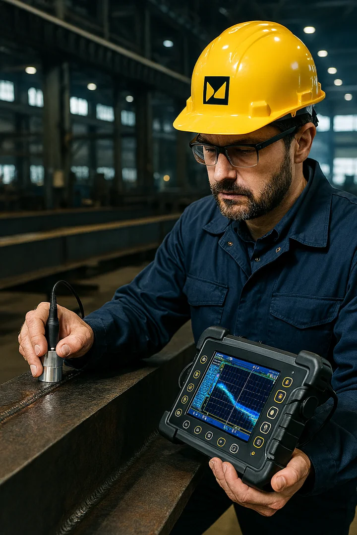
Non-destructive testing (NDT) – a general term for methods of testing materials and products without their destruction. NDT methods include radiographic (X-ray/gamma), ultrasonic, magnetic particle, capillary, eddy current, acoustic emission and visual inspection. Radiography is one of the types of radiation NDT, along with gammagraphy.
The key advantage of radiography is that it provides a clear x-ray picture of internal inhomogeneities. We can say that this is “transmission” flaw detection – we see hidden cracks and voids, like shadows in a photograph. For example, when inspecting welds on a pipeline, X-rays can detect lack of penetration or pores that are not visible from the outside. In industry, radiographic testing is often referred to by other terms: X-ray testing, radiographic testing, X-ray flaw detection - all these names describe one method. It is widely used along with ultrasound and visual inspection (VII), and each method has its own niche application (for more information about the different methods, see our article Non-destructive testing of welds: a review of methods and equipment). But radiography is often indispensable when quality control of welded joints of thick-walled or critical structures is required.
It is worth noting that non-destructive testing is only part of the quality assurance complex. There are also destructive tests of materials: for example, testing the tensile strength of metal using a special tensile testing machine or assessing the strength of concrete using methods such as sclerometry (concrete testing: methods for determining strength). However, quality control of welds is most often carried out using NDT methods, among which X-ray testing of welded joints occupies a special place. Below we will analyze in detail its application, implementation technique and safety measures, based on real examples and industry experience.
Applications of radiographic testing in industry
Radiographic inspection is used today in a wide variety of industries. Wherever there are critical metal structures or pipelines, weld X-raying helps ensure their reliability. Let's look at the key areas of application:
Construction and metal structures
In the construction industry, quality control of welds of load-bearing structures is the key to the safety of buildings and structures. For example, when constructing bridges and building frames, X-ray inspection of welds at critical components is mandatory. There was a case in my practice: during radiographic inspection of the joints of the steel frame of a sports complex, we discovered a defect in the welded joint - a longitudinal crack, invisible from the outside. The welding was redone in a timely manner, which prevented a possible disaster. Radiography of metal structures makes it possible to identify defects in metal structures - cracks, lack of penetration, pores - even at the construction stage, without waiting for them to manifest themselves in operation.
Mechanical engineering and equipment production
In machine-building plants, radiographic testing is used to check the quality of critical parts and assemblies. For example, an industrial X-ray machine is indispensable when monitoring castings and forgings for the presence of internal cavities, gas pores, and shrinkage cavities. During the operation of the metal, the following defects may appear: fatigue cracks, internal tears, delaminations - especially in thick parts. Even at the production stage, X-ray flaw detection reveals metal defects (types of internal defects), such as shrinkage cavities in castings or lack of penetration in equipment welds. For example, in the manufacture of high-pressure vessels (boilers, tanks), each seam is x-rayed - this is a mandatory requirement of safety standards. For thick-walled products, gamma flaw detection with isotopes is also practiced, but the principle is the same - radiography. The quality of welds of machine parts directly affects the service life of the equipment, therefore, critical industries (energy, transport engineering, etc.) cannot do without radiographic control.
Oil and gas industry and pipelines
This is where radiography is most widely used. Diagnostics of pipelines - from main oil and gas pipelines to heating network pipes - is unthinkable without the radiographic method. Non-destructive testing of pipelines includes mandatory inspection of welded joints during pipeline construction and selective testing during operation. Pipeline X-ray allows you to detect dangerous defects: lack of penetration of the root of the seam, wedging, porosity, cracks. For example, during the construction of main gas pipelines, standards require 100% control of pipeline welds by radiographic or similar methods. In my practice, there was a project to diagnose main pipelines with a diameter of 720 mm, where we used a special X-ray crawler - a self-propelled device moving inside the pipe. This X-ray crawler is equipped with an X-ray generator and radiographic film (or digital detector) and automatically scans each joint from the inside. The advantage is that there is no radiation into the external environment, which is especially important for long pipelines. For example, model X-ray crawler for pipelines MIT RAY XC allows you to control seams inside pipes with a diameter from 219 mm to 1524 mm at a distance of up to 12 km autonomously. This approach speeds up the inspection of welded joints of long-distance pipelines and increases work safety. Of course, during the repair and operation of pipelines, X-rays are also used - for example, if there is a suspicion of corrosion damage or cracks in the seams on existing water pipelines, gas pipelines, or oil pipelines. Although ultrasound or in-pipe scanners are more often used in operation, pipeline radiography remains relevant for quality control of repair welded joints.
Practical example: At one oil refining company, regular X-ray inspection of pipelines allowed early detection of a crack in a weld at a pipeline bend. The crack was caused by pump vibration (fatigue defect) and could lead to leakage. The x-ray clearly showed the defect, although external examination did not reveal the problem. After replacing the section, the accident was avoided.
Aerospace and defense industry
Here, too, non-destructive testing is particularly strict. X-ray flaw detection is used to inspect turbine blades, engine parts, aircraft and missile components. For example, fluoroscopy (dynamic radiography) is used to check the continuity of composite materials, soldering of honeycomb structures, etc. Metal fluoroscopy is a method close to radiography, but in real time: defects are visible on the image intensifier screen without film. This method is convenient for quickly checking complex products (for example, checking soldering in electronics or searching for foreign inclusions in cast parts). However, classical radiography of welds with film or a digital detector is still used when a documented result with high sensitivity is needed.
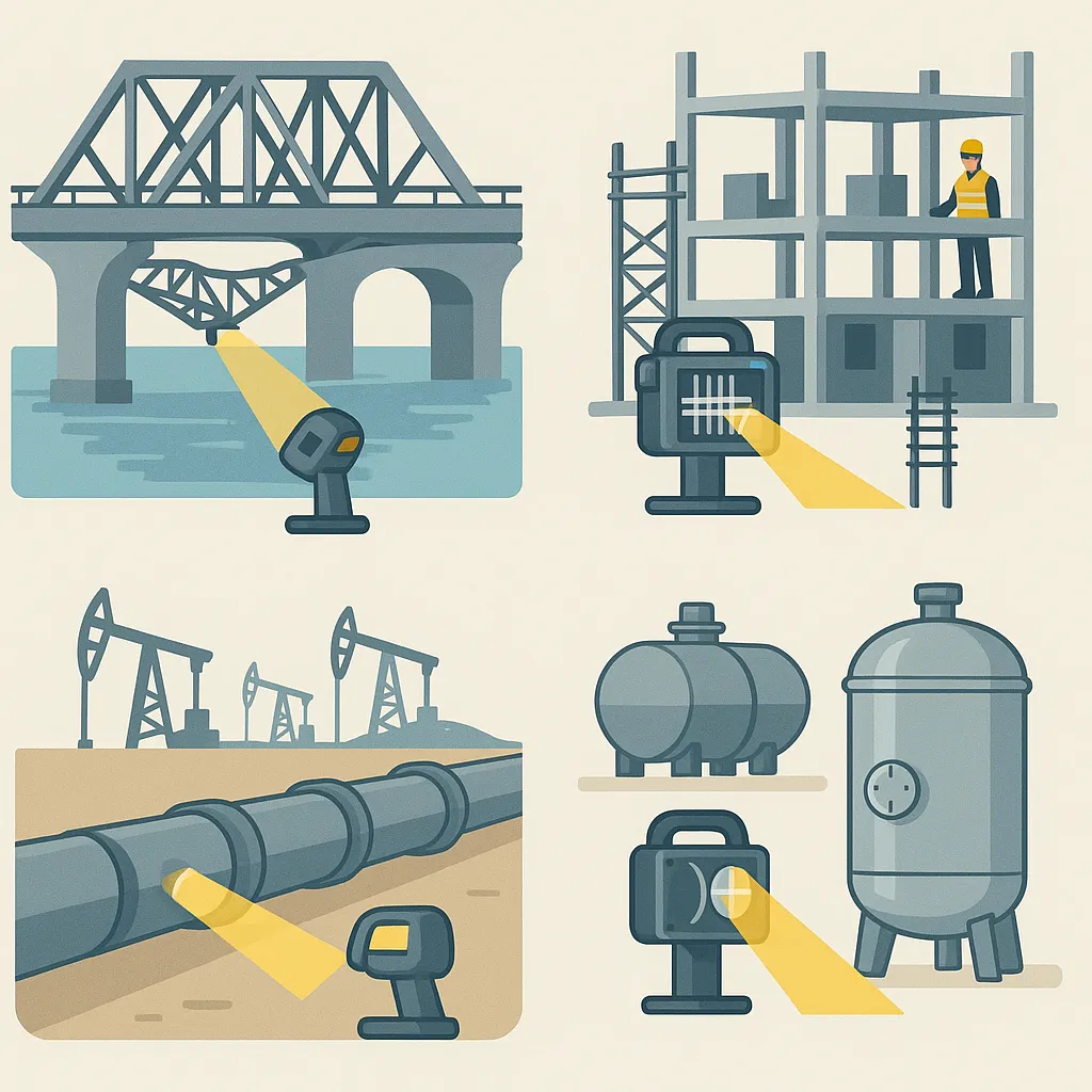
To summarize, X-ray inspection is used wherever the reliability of metal products and structures is critical. It is especially effective for quality control of welded joints in critical components. That is why regulatory documentation (building codes, Rostekhnadzor rules, etc.) often prescribes the radiographic method as mandatory. In the following sections, we will consider the design of X-ray flaw detectors and testing technology in more detail.
The operating principle of an X-ray flaw detector and the equipment used
An industrial X-ray machine is similar in principle to a medical one, but has a higher radiation energy and is adapted for work in field and workshop conditions. The main unit is an X-ray tube, which generates a beam of X-ray radiation when a high voltage is applied. In industrial flaw detection, portable pulse-type X-ray machines are often used: they create short, high-energy pulses that make it possible to illuminate metal of a given thickness. The X-ray tube can be in a glass or metal sealed shell. For example, modern portable devices such as MIT RAY XQ series use a glass X-ray tube - a reliable and proven option that provides stable radiation. The X-ray flaw detector also contains a high-voltage generator unit, a cooling system (in powerful units - oil cooling or air blowing), and a control unit that allows you to set radiation parameters (voltage in kV, current or pulsed energy, time exposure).
Types of X-ray flaw detectors
Equipment for radiographic testing is very diverse in design and purpose:
Stationary X-ray units
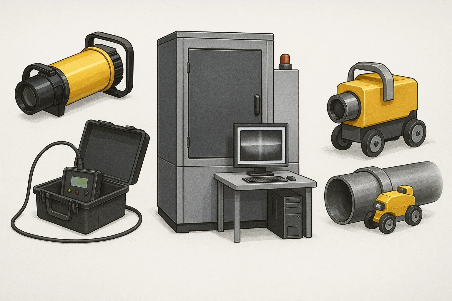
Used in non-destructive testing laboratories. Such devices can have voltages from 160 kV to 450 kV and higher. They are designed for illumination of large-sized and thick-walled products. For example, a stationary industrial X-ray with a voltage of 250–300 kV is capable of examining steel castings 50–100 mm thick. Often, stationary installations are mounted inside special protective chambers (X-ray chambers) with thick concrete or lead walls to ensure radiation safety.
Mobile portable X-ray machines
The most common type in the field. They are relatively light (usually 10–40 kg) and are designed to operate from the mains or generator. Portable devices can be directional radiation (the beam comes out of the “window” of the tube in one direction) or panoramic (circular radiation, like a gamma source). Most modern portable devices are directional, making it easier to ensure safety and block unnecessary scattering. An example of such equipment is an X-ray flaw detector MEAT RAY XQ. This installation is available in several modifications, differing in maximum radiation energy. Below is a table with the main characteristics of the XQ series:
Table 1. Example of technical characteristics of portable X-ray devices of the MIT RAY XQ series (directional portable X-ray flaw detector with a glass tube):
| Model | Maximum thickness of steel penetration, mm | Voltage, kV | Generator weight, kg |
|---|---|---|---|
| XQ 160S | 18 | 60–160 | 12,5 |
| XQ 200S | 29 | 100–200 | 24 |
| XQ 250S | 40 | 150–250 | 34 |
| XQ 300S | 50 | 170–300 | 41 |
Note: With increasing energy (voltage), the penetrating ability increases - for example, the 300S model allows you to penetrate up to 50 mm of steel. However, the dimensions and weight of the device are increasing. All models are equipped with a digital control panel and protection systems (overheating, overvoltage), ensuring safe operation.
Specialized X-ray systems (crawlers)
As already mentioned, in-line X-ray scanners, or X-ray crawlers, are used to inspect long pipelines. They are a battery-powered, self-propelled cart carrying an X-ray emitter and receiver (film or detector). The crawler moves inside the pipe to the weld joint and there it scans the weld from the inside. It is very effective and safe because... absorption of radiation by the pipe prevents external exposure of personnel. An example is the MIT RAY XC series, the characteristics of which were given earlier: model XC-219/160 for pipes ⌀219–377 mm, voltage up to 160 kV, range up to 8000 m; more powerful XC-508/300 for pipes up to ⌀1524 mm, voltage 300 kV, range up to 12 km, etc. Such X-ray devices for non-destructive testing of pipelines are quite expensive, but pay for themselves on extended objects (main oil and gas pipelines).
Gamma flaw detectors
Although formally this is not x-ray control, but gamma control, we will mention them as a related tool. A gamma flaw detector uses a radioactive source (usually iridium-192 or selenium-75, less commonly cobalt-60) to produce gamma rays, which have properties similar to x-rays. The advantage is complete autonomy (no current required, compact size). The disadvantage is constant radiation (the source is always “phonic”), which creates increased radiation risks. Gamma sources are used on remote construction sites (for example, when repairing a pipeline in the tundra, where there is no electricity). However, where possible, they are gradually being replaced by portable X-rays, because the latter are safer (they only emit when turned on) and radiation safety is easier to manage. In Russian terminology, both methods (X-ray and gamma) are combined under the name “radiation monitoring” or radiographic method, and abroad they also often say RT (Radiographic Testing), without separating X and γ. For example, GOST 7512-82 establishes uniform requirements for x-ray and gamma-ray examination of welds[2].
Principle of radiographic inspection
The essence of the method is the absorption of radiation by the material. X-rays passing through metal are attenuated - the degree of attenuation depends on the thickness and density of the material. A defect (such as a void or pore) has less absorption capacity than the surrounding metal, so more intense radiation escapes behind the defect. On X-ray film or detector, these places are recorded as darker spots (with classical film radiography, the defect appears dark against a light background, because more rays reached and illuminated the film). Thus, we obtain a shadow image of the internal structure of the product.
Mathematically, the attenuation of rays is described by the exponential Bouguer–Lambert law:
$I = I_0 \, e^{-\mu x}$
Where I₀ – initial intensity of X-ray radiation, I – intensity after passing through a layer of material thick x, μ – linear attenuation coefficient (depends on the material and energy of the rays). In areas where there is a defect within the material (for example, internal metal defects: voids, gas inclusions or slag), the effective thickness x less, and I will be more, which is recorded on the receiver.
Note: The sensitivity of the radiographic method is assessed through the minimum size of the defect that can be detected on the image. In practice, sensitivity standards are used - wires or stepped samples. According to GOST 7512-82, the sensitivity of the control is determined by the thinnest wire visible on the radiograph [1]. For example, if a wire with a diameter of 0.1 mm is visible in an image with a product thickness of 10 mm, the sensitivity is ~1%. The radiographic method usually provides a sensitivity of about 2% or higher (with optimal parameters and the use of fine-grained film or a high-resolution digital detector).
Of course, to obtain a high-quality image, one device is not enough. Consumables and accessories are needed: radiographic film (if the method is classic film), cassettes and intensifying screens (lead plates) to improve quality and reduce exposure, marker signs (for marking the side, image number, seam identification), as well as flaw detection standards - for example, the above-mentioned wire sensitivity indicators (they are also called penetrameters). All these accessories are regulated by standards: GOST 15843-79 sets the sizes of films, screens and cassettes[3], standards for films and developers, GOST 20426-82 – testing techniques using film, GOST 23764-79 – requirements for gamma flaw detectors, etc.
The current trend in radiographic inspection is the transition to digital technologies. Computed radiography (CR) appeared with photostimulated plates instead of film, and digital radiography (DR) - direct image recording with a digital detector (flat panel). Standards already take this into account: for example, the international standard ISO 17636-2:2013 regulates radiographic inspection with digital detectors, providing equivalent sensitivity to film[4]. Russian equivalents GOST ISO 17636-1-2017 (for film) and GOST ISO 17636-2-2017 (for digital detectors) have been put into effect since 2021[5]. The introduction of digital systems makes it possible to speed up image acquisition (instant display), improve archiving (no need for bulky film archives), and even use software image processing to improve the visibility of defects. However, classic film is still widely used, especially in the field, due to its simplicity and familiarity.
Radiographic control in the technological process
In production, X-ray inspection is usually integrated into the quality process chain. For example, quality control of welding of a large product may include: admission of welders according to their qualifications, visual measurement control (VII) of each seam immediately after welding, elimination of visible defects (sagging, undercuts), and then radiographic inspection of the most critical seams. Based on the results of radiography, a decision is made: if defects in welds exceeding the permissible limits are detected, the seam is subject to repair (overwelding) and then inspection of the welds after welding is carried out again until a satisfactory result is obtained. This cycle can be repeated, because the main thing is to achieve the required quality of the seam in accordance with the standards. In the next section, we'll take a closer look at defects and quality assessment criteria before moving on to safety issues.
Expert advice: When choosing equipment for radiographic testing, it is important to consider the thickness and material of the objects being tested. The most powerful device is not always needed - for thin-walled structures 100–160 kV is sufficient. Buy a flaw detector buy from trusted suppliers, paying attention to the availability of service and a protection kit. The price of an X-ray machine increases with the increase in maximum voltage and power, but there is no need for excessive characteristics. Correct selection of the installation will provide an optimal balance between cost and control efficiency.
Technology for radiographic testing of welded joints
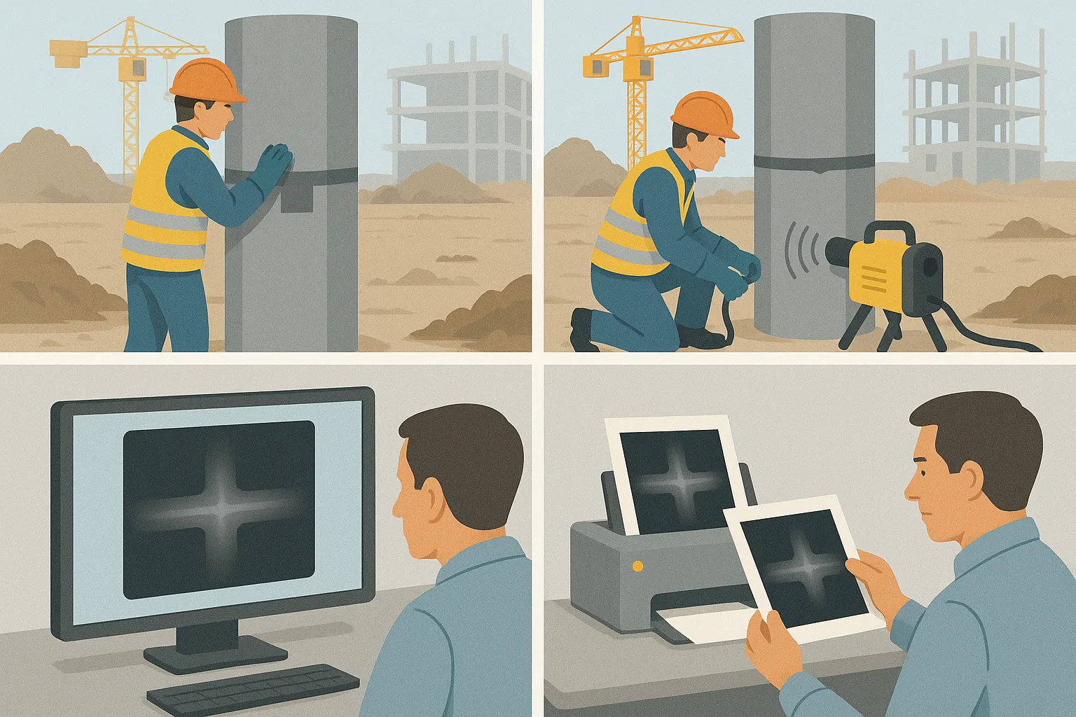
Now let's look at the practical aspects of how to properly x-ray welds. The radiographic testing process consists of several stages that require strict adherence to the methodology and safety rules:
1. Preparation of the control object
The weld to be X-rayed must be cleaned of dirt, metal splashes, and scale so that extraneous deposits do not distort the X-ray image. Visual and measuring inspection of welded joints (VII) is carried out: the geometric parameters of the weld (leg, convexity), and the absence of external defects (cracks, undercuts) are checked. If unacceptable surface metal defects are detected, they are eliminated before radiography. Also at this stage, the installation location of the film/detector and the radiation source is marked, and markings are attached (for example, lead letters indicating the seam number, side, direction of illumination).
2. Equipment installation
Depending on the size of the object and the type of device, the exposure scheme is selected. The classic situation is single-wall transmission (for relatively thin objects): an X-ray tube on one side of the seam, a film (in a light-proof cassette) on the opposite side. The distance from the tube to the object (focal length) is selected according to standards, usually not less than a certain minimum, in order to reduce geometric non-resolution (blurring of the defect image). The greater the distance, the sharper the image, but more power or exposure time is required. Sometimes double-wall transmission is used - for example, for small-diameter pipes, when the source and film are located outside the pipe, and the rays pass through both walls and two layers of the seam. In this case, two images of the overlapping seam are projected on the film at once, so the method is applicable only for small diameters and requires careful positioning of the film. In the case of large pipes, as mentioned, in-line inspection (crawler) or installing the source inside and the film outside (panoramic inspection) is optimal. At the installation stage, it is important to place flaw detection sensitivity standards (for example, wire ones) on the test object - usually on the side of the seam, in order to then determine in the image the achieved sensitivity of testing based on visible wires of a certain diameter.
3. Exposure mode calculation
The operator sets parameters on the X-ray machine: voltage (kV), current or number of pulses, exposure (irradiation time). These parameters are selected based on the thickness and density of the material, the sensitivity of the film or detector, and the distance to the object. There are usually standard mode maps or programs that make mode selection easier. If you set the dose too low, defects may not appear (the picture will turn out “underexposed”), and an excessive dose will lead to overexposure (image details will “burn out”). A qualified flaw detectorist, based on his experience or reference tables, selects the optimal mode. For example, 20 mm thick steel may require ~180 kV and 5 mA⋅min exposure to medium speed film.
Formula for calculating attenuation: In radiography, the inverse square rule is used to estimate dose: the radiation intensity decreases as the square of the distance. If at a distance r₁ We got an acceptable blackness of the image within a period of time t, then at a greater distance r₂ with the same parameters, the exposure should be increased by approximately (r₂/r₁)² once. This is important to consider if it is impossible to bring the device closer to the object. The concept of a semi-absorbing layer is also used: a thickness of material that reduces the intensity by 2 times. For example, for ~3 mm steel, the flux is reduced by half for ~200 kV x-ray radiation. Knowing the equivalent number of half-layers, the required exposure for the required thickness can be calculated.
4. Ensuring safety before exhibiting
Even before turning on the radiation, it is necessary to create radiation-safe conditions. Warning signs and barriers are installed around the control area. Typically, for portable devices, an area within a radius of 20–30 m is considered dangerous (the exact radius is calculated based on the dose rate of a particular device). All strangers are removed from this area. The operator and assistant occupy a safe shelter - behind a concrete wall, an earthen bank, or at a distance at which the dose drops to an acceptable level. According to radiation safety standards (NRB-99/2009), exposure of group A personnel should not exceed 20 mSv per year (on average), which is achieved by strict adherence to work regulations [6]. Therefore, every turn on of the X-ray machine is accompanied by a command and a convincing connection - so that no one accidentally ends up in the radiation zone. The operator turns on the high voltage only after making sure that the area is clear. There are locks in laboratories: the X-ray chamber door is closed - only then can the machine be turned on. In the field, responsibility lies with the NK team. Also, personnel must wear personal dosimeters (check the accumulated radiation dose).
5. Exposure (illumination)
The irradiation process itself usually takes from several seconds to several minutes, depending on the required exposure. With pulsed devices, a series of pulses can be generated. At this time, radiation (X-ray or gamma) passes through the controlled area and affects the recording element (film or digital detector). After the end of exposure, the device turns off (or the gamma source returns to the container). The film is considered "shot".
6. Image development and acquisition
If classic film is used, the next step is its photochemical processing. In a specialized darkroom or in the field in a portable darkroom, the film is developed in a developer solution, washed, fixed with fixer and dried. The result is a clear x-ray (radiographic image) showing the internal structure of the suture. With digital methods, this is the stage of either scanning the plate in a CR scanner (for photographic plates), or simply reading the image from the detector to a computer (DR). The digital image can be immediately displayed on the laptop screen. Digital systems often have software to improve contrast, zoom, automatically measure defect size, etc. But when assessing the results, it is important to comply with the requirements of the standard - for example, in ISO 17636-2 specifies minimum resolution and contrast requirements for digital radiographs to equivalently replace film[4].
7. Interpretation of results (decoding radiographic inspection defects)
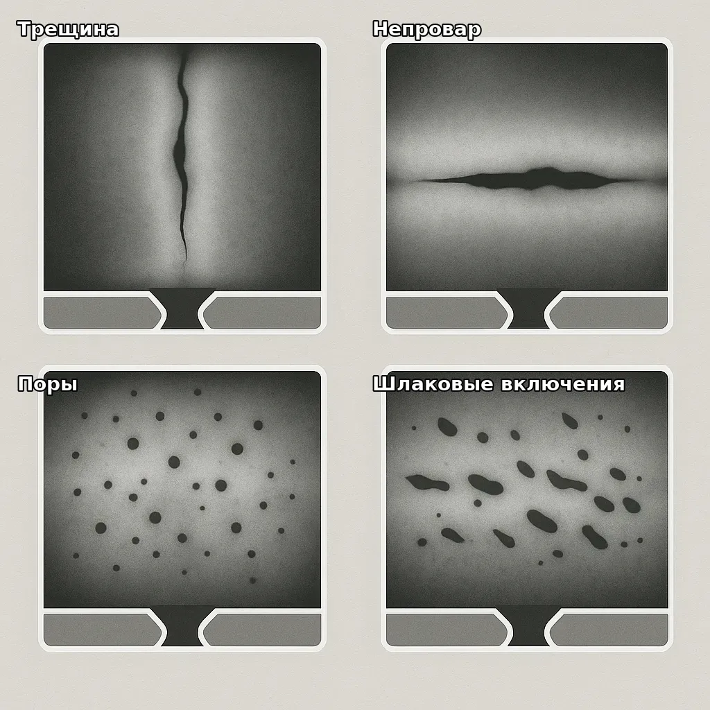
This is, perhaps, the most important stage - the assessment of the radiographic image by a qualified flaw detector (an operator of level II NDT qualification, as required by the standards). The specialist views the image on a X-ray viewer (a special illuminated screen) or on a computer, if the image is digital, and identifies indications of defects - darkening or lightening that differs from the normal structure. The defects are deciphered: the types of defects are determined by shape and location. For example, small round dark spots scattered in the base metal of the weld are probably pores. A long broken dark line along the axis of the seam is possibly a lack of penetration of the root or in the middle of the seam. A narrow sharp dark line is a crack (if it is oriented almost perpendicular to the rays, it will be visible). Vague indistinct spot - may be slag or slag inclusion, or undercut, depending on the context. Experience and knowledge of typical radiographs come into play here. Regulatory documents provide significant assistance. For example, GOST 23055-78 establishes a classification of radiographic testing results: seven classes of welded joints according to permissible dimensions and number of defects[7]. Simply put, the standards contain criteria for which defects are considered acceptable and for which the seam is rejected. This is an assessment of the quality of welds. For example, for a high-pressure pipeline, single pores with a diameter of no more than 1 mm may be allowed, but cracks are absolutely unacceptable in any size (zero). For less critical structures, tolerances are softer. A flaw detector, having discovered defects in the image, measures their sizes (a scale is often marked on the image, or the size of the indications can be estimated from the image of the sensitivity standard). Then he compares it with the norms: if it exceeds the permissible limit, the result is “unsatisfactory.”
8. Documentation of results
Based on the results of the inspection, a radiographic inspection protocol is filled out, which indicates the method, mode, sensitivity, and lists the identified defects of welded joints with classification (for example: “lack of penetration of the root of a weld 8 mm long, exceeding the permissible size of 5 mm according to GOST ...”). With digital radiography, /images are usually saved in a file and can be attached to a report. With film, the films are marked and stored in the enterprise archive as proof of quality. The protocol also includes a conclusion: is the unit suitable or not, recommendations for repair, if defective.
Common mistakes during radiographic testing: Failure to comply with the technology may lead to false conclusions. Here are some common mistakes:
- Incorrect exposure: an overdeveloped or underdeveloped photograph in which defects are masked. The solution is to accurately calculate the mode and make test exposures.
- Beam and seam misalignment: if the source has been displaced, defects may not be projected clearly. It is important to correctly center the X-ray machine relative to the object.
- Light flares, artifacts on film: may be considered defective. It is necessary to protect the film from light exposure, dust, scratches, and when reading to distinguish artifacts (for example, a scratch on the film has characteristic edges).
- Identification violation: mixed-up or incorrectly labeled photographs. This risks the defect being attributed to the wrong seam. Each frame must have side labels (for example, the letters “B” and “H” - top/bottom of the pipe) and a number.
- Insufficient sensitivity: did not use the required penetrameter - and minor defects may go unnoticed. You should always monitor sensitivity according to GOST (visibility of control defects).
- Neglect of safety: sometimes they are in a hurry and do not cordon off the area sufficiently, putting others at risk. This is a grave mistake - radiation safety comes first, even if you have to spend extra time.
So, a well-executed method of monitoring welds by radiography gives valuable results - we learn about internal defects that are invisible to the eye, and we can take action. However, not all types of defects are equally accessible to x-rays. Let's talk a little more about the types of defects and which methods are best at identifying them before moving on to a discussion of safety and regulations.
Typical defects in metal structures and assessment of radiographic results
Welded seams and metal products may contain a variety of defects - in origin, shape, and danger. Defects in metal structures are conventionally divided into production (arising during manufacturing: welding, casting, processing) and operational (arising from loads, corrosion, wear). Radiographic testing is most effective for identifying manufacturing defects in welding and casting, as well as some operational ones if they are internal discontinuities. Let us list the main types of defects and evaluate how they appear on an x-ray and other methods:
Cracks
These are breaks in the continuity of the metal. There are hot cracks in welds (occur during metal crystallization) and cold, or operational fatigue cracks. On a radiographic image, a crack is visible if its plane is oriented close to perpendicular to the rays. Then it looks like a thin, sinuous dark line. However, if the crack is located along the direction of transmission (for example, a crack along the depth of the seam, parallel to the beam), then it may not be detected on an x-ray [8] - the beam passes along it and does not provide contrast. Therefore, the standards warn that radiography does not guarantee the detection of such cracks. To detect cracks, especially superficial ones, ultrasonic testing (the echo from a crack is easily caught) or penetrant flaw detection (for open cracks) is more effective. Ideally, methods are combined. But if a crack is caught on an x-ray, this is an obvious defect: not a single standard allows a crack. There is only one solution - cut out/digest the area.
Lack of penetration and lack of fusion
These are violations of welding technology: lack of penetration of the root of the weld, incomplete fusion along the edges. On a radiograph, root failure usually appears as a straight, dark line along the center of the joint (where the root should be), often with sharp edges. Lack of fusion along the edge - a dark line along the border of the weld with the base metal. X-rays are good at revealing lack of fusion if the seam is oriented normally to the beam. In practice, precisely such defects have been caught many times - they are dangerous because they greatly reduce the strength of the connection. The permissible size of lack of penetration is very small (several mm in length) even for low categories of seams, and for critical seams, lack of penetration is completely unacceptable. Alternatively, ultrasound can also detect lack of fusion, but may confuse them with cracks; an experienced operator is required. X-ray inspection gives a more clear picture of lack of penetration, especially at pipeline joints.
Pores and gas inclusions
These are small spherical or elongated cavities formed due to gas in the melt during welding or casting. Pores appear as round dark dots on an X-ray. The pore size ranges from microscopic to several millimeters. Single small pores are usually allowed by standards (in limited quantities), but accumulation of pores (porosity) or large pores are already a problem. Radiography is the best method for detecting porosity; it is directly tailored to such metal defects. Ultrasound does not recognize very small pores well - the signal is weakly reflected from small gas spheres. Therefore, for example, defects in rolled metal such as gas bubbles (if they exist inside the ingot/blank) are best monitored radiographically or through transmission (if the thickness allows).
Slag inclusions and non-metallic inclusions
In welds, slag inclusions are often found - residues of flux and slag that have frozen inside the metal. They are usually oblong in shape and can be single or in chains. On X-ray, slag produces an elongated, dark image, often with fuzzy edges (as opposed to pores, which are sharper and rounder). Small inclusions can be allowed, but if they form a continuous chain along the entire length of the seam, the seam is rejected according to the quality category. Non-radiation methods can also help here: ultrasound detects large slag inclusions as scattered signals, but it can also miss small scattered pores/slags. So, radiographic testing of welded joints is especially effective for identifying volumetric inclusions – pores and slag.
Undercuts, burns (welding shape defects)
An undercut is a groove at the edge of a seam, a burn is a through penetration of the wall (hole). These defects in the surface of the metal after welding are more likely to be detected visually, but x-rays also record them; if, say, a burn-through is fused with metal on top, there will be a cavity under the burn-through, visible in the image. However, for undercuts and other surface surface defects (scratches, tears), the VIR or capillary method is better suited. Radiography is still focused on internal defects.
Delaminations and cracks in the base metal
Rolled products may have flat delaminations (for example, a sunset-type defect - a torn layer rolled into a plate). X-rays reveal such defects in rolled metal poorly, because they lie parallel to the plate and do not create a difference in thickness for the rays. Ultrasonic sound is effective here. If there are volumetric inclusions in the plate (slag, non-metallic), radiography can show them, but in thick rolled products (more than 40-50 mm) a very powerful source or gamma with cobalt-60 is required, and this is troublesome. Therefore, ultrasound is often used for sheets. However, to control, say, railway rails, radiography was once used (they looked for internal cracks, thermal rolling defects), now they have also switched to ultrasonic testing mainly.
To summarize the defects: the X-ray inspection method perfectly detects volumetric defects (pores, inclusions, cavities) and quite well - some extended defects (lack of fusion, cracks), if they are oriented favorably. But it is ineffective for planar defects running parallel to the rays or surface. Therefore, in practice, for high reliability of testing, a combined approach is used: radiography + ultrasound, radiography + magnetic particle method (for surface cracks), etc. The quality of welds is assessed comprehensively. Standards (eg GOST 23055-78, ISO 5817) classify defects and set tolerances. The main thing is that no dangerous defects should escape.
Below is a small comparison table showing which NDT methods are better at detecting different types of defects in welded joints:
Table 2. Comparison of non-destructive testing methods of welds for detecting defects
| Defect type | Radiographic control (X-ray/gamma) | Ultrasonic testing (UT) | Visual and measuring control (VIC) |
|---|---|---|---|
| Lack of penetration, lack of fusion | Fine – appear as lines on the x-ray (if oriented) | Fine – give a clear echo sounder signal | Not visible (internal defects) |
| Cracks (through thickness) | Удовлетворительно – видны, если ориентированы к лучу; могут не проявиться при неудобном направлении | Great – reflected as a strong signal, detected by an echoscope | Partially – only cracks emerging to the surface are visible |
| Surface defects (undercuts, cracks on the surface) | Poor – do not provide contrast (or very little) | Bad - ultrasonic inspection does not see open surface thin cracks without special inclined probes | Great – easily fixed visually and using a measuring tool |
| Thick-walled objects (>50 mm) defects inside | Limited - requires a very powerful source or long exposure; the quality is worse | Fine – the penetrating ability of ultrasonic testing is high on thick metal | Not applicable |
| Documenting results | Eat – the film/digital photograph is stored and serves as evidence | Partial – results in the form of a report, you can save flaw detector readings (A-scan, B-scan) | Eat only the inspector’s conclusion, photographs of the surface if necessary |
As you can see, radiography wins in clarity and detection of volumetric imperfections, ultrasound – in identifying cracks and in inspecting thick products, and the visual method – in catching external flaws. It is no coincidence that all three are often used sequentially: first VIR (surface), then X-ray or ultrasound (volume). In any case, the radiographic method remains one of the most effective methods for quality control of welded structures due to its versatility and image reliability.
Safety requirements for x-ray inspection
X-ray radiation is ionizing, and working with it requires strict adherence to safety measures. Radiation safety is a key aspect when organizing radiographic control in production. An error in handling X-ray equipment can lead to exposure of people, so there are detailed standards and rules that every flaw detector must adhere to.
Basic rules of radiation safety
Safety precautions when working with X-ray equipment are regulated by both national standards and sanitary norms. In Russia, the basic document is Federal Law No. 3-FZ “On Radiation Safety of the Population” and the sanitary rules arising from it. Designed specifically for non-destructive testing SanPiN 2.6.1.3164-14 “Hygienic requirements for ensuring radiation safety during X-ray flaw detection.” This document covers everything from requirements for laboratory premises to procedures for radiation monitoring of personnel. According to SanPiN 2.6.1.3164-14, the X-ray flaw detector is considered a source of ionizing radiation, potentially hazardous to health, and all work with it must be carried out by trained personnel in strict compliance with the regulations [9][10]. The main principle is continuous monitoring and minimization of doses. Here are a few key radiation safety rules for X-ray monitoring:
Zoning and fencing
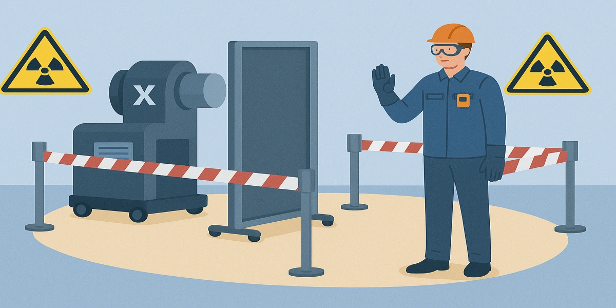
The radiography site should be isolated from personnel not involved in the inspection. During the exposure, a barrier (signal tape, cones, fences) with warning signs “Danger, Radiation!” is installed around the source. The radius of the danger zone is calculated based on the dose rate of the device. For stationary device laboratories, protective chambers are built, the walls of which contain lead, barite concrete or other absorbers so that radiation does not escape outside. In field conditions, mobile shelters are sometimes used - for example, lead screens or containers where the operator hides. Radiation hazard signs must be posted.
Radiation dose and time
The ALARA principle (As Low As Reasonably Achievable) states that exposure should be as low as possible. This is achieved by reducing the operating time of the source (make only the necessary exposures), using technical means of protection (shield the source as much as possible, use collimators - attachments that limit the beam at an angle). Group A personnel (working with radiation) wear individual dosimeters (thermoluminescent, electronic) and regularly submit them for dose reading. It is controlled to ensure that no one exceeds the annual limit. As stated in NRB-99/2009, for personnel this is 20 mSv/year on average, but not more than 50 mSv per year [6] - these standards are built into the internal instructions of enterprises. In practice, the real doses of flaw detectors are much less than the limits if safety measures are followed - usually units of mSv per year.
Personnel training and admission
Only employees who have undergone special training are allowed to work with X-ray machines. Each radiographer must have a radiation safety certificate (training and testing of knowledge of the rules are carried out annually or once every 3 years). In addition, personnel undergo mandatory medical examinations to ensure that there are no contraindications to working with AI (for example, diseases incompatible with periodic radiation exposure). Radiation safety briefings are carried out upon each admission to the facility: the officer responsible for radiation safety explains the radiation protection scheme, zones, actions in case of an emergency, etc. The list of persons authorized to work with a particular X-ray machine is approved by management in advance[11]. No unauthorized persons or untrained workers may turn on the flaw detector without permission - this is strictly prohibited.
Equipment verification and documentation
X-ray installations must have a passport, certificate, verification marks (for dosimetric devices) and maintenance marks. The workplace is periodically certified for compliance with standards (once a year, radiation levels around are measured, the serviceability of signal equipment is checked - stationary installations have an “X-ray on” signal lamp). Regulatory documents should also be available: production instructions, emergency instructions (what to do if a gamma source gets stuck, for example), logs of personnel exposure doses and a log of device switching on.
Personal protective equipment
In the classical sense, lead aprons and gloves are rarely used in industrial radiography, because usually everything is done remotely. However, if you have to hold the film or cassette close to the source before exposure, the flaw detector can wear a 0.5 mm Pb equivalent lead apron and gloves - this will protect against scattered radiation. You cannot constantly work under the rays - PPE is not a panacea, they only complement the basic measures (time, distance, screens). In any case, personnel are required to wear a dosimeter as part of their equipment.
Work area control
Before starting work, background radiation in the area is measured. After turning on the installation, dosimetrists or the operators themselves check the dose rate at the border of the hazardous zone, making sure that it does not exceed the permissible level (for example, no more than 0.3 μSv/h at the border of the zone where people may be - such a requirement can be set locally). If an excess is suddenly detected, work is stopped and protection is strengthened or the zone is expanded.
Prohibited tricks
It is strictly prohibited to conduct X-ray examinations of people for production purposes (for example, to “examine” a worker’s hand to check how he holds a tool) - such incidents are described only as examples of gross violations[12]. Also, you should not leave the source unattended, carry the X-ray machine with it on, etc. Any actions outside the regulations are considered an emergency. In case of accidents (for example, locking the Ir-192 source outside the container, loss of control over radiation), liquidation plans are in place, people are evacuated, and regulatory specialists are called in (often the Ministry of Emergency Situations does this).
Regulatory and Safety Standards
At the legislative level, radiation safety is regulated by several levels of documents:
Federal laws and regulations
Already mentioned FZ-3 “On radiation safety of the population”, as well as FZ-52 “On sanitary and epidemiological well-being.” They provide a common basis. Industry rules - for example, Rostechnadzor rules for hazardous facilities - may require the development of special regulations for radiography at such facilities.
Sanitary standards (SanPiN and OSPORB)
Key: SanPiN 2.6.1.2523-09 – NRB-99/2009 (radiation safety standards)[10], and SanPiN 2.6.1.3164-14 – hygienic requirements for X-ray flaw detection. Also fundamental OSPORB-99/2010 – basic sanitary rules for ensuring radbez. They detail the requirements for laboratory premises, for registration and accounting of radiation sources, for personnel training, formulas for calculating radiation protection, etc. are provided. For example, SanPiN 2.6.1.3164-14 determines that the design of an X-ray flaw detection laboratory must be agreed upon with the sanitary inspection authorities, the walls are calculated for thickness taking into account the voltage of the apparatus and the operating mode, and the presence of interlocks and alarms is mandatory[13].
Radiation Control Standards
From a metrological point of view, GOST 8.638-2013 (metrological support for radiation monitoring) determines how dosimeters, radiometers and other equipment are checked[14]. A GOST 20426-82 (radiographic control, rules) and a number of others - how to ensure the quality of the control itself. There is even a standard GOST R 55776-2013 “Non-destructive radiation monitoring. Terms and Definitions”, where all terms such as radiographic method, x-ray image, absorptivity, etc. are introduced. The correct use of terms is also part of the culture of safety and quality: for example, staff must clearly understand the difference between radiography (using film) and fluoroscopy (observation on a screen in real time).
It is important to note that all companies performing radiographic testing must have the appropriate licenses. In Russia, activities with sources of ionizing radiation are subject to licensing by Rostechnadzor (for production facilities) or Rospotrebnadzor - depending on the situation. It is illegal to use an industrial X-ray machine without a license. To obtain a license, an organization must provide documents on employee training, the presence of premises or procedures that ensure safety, registered radiation sources, etc.
Safety first: As an experienced specialist, I always remind young flaw detectors: there is no production task that costs health or life. If conditions do not allow for safe X-ray inspection (for example, people work nearby and there is nowhere to evacuate them, or the X-ray machine is faulty and the radiation is not blocked), the work must be rescheduled or the inspection method must be replaced. Radiation safety is not a formality, but a strict rule. In my practice, there was a case when a radiographer saved an installer: before starting to clear the pipe, he noticed that the fitter, contrary to the instructions, remained working behind the column in the control zone. The work was immediately stopped, the person was removed - perhaps thanks to this, his exposure to radiation was prevented. Remember that X-rays are invisible, but their effects are very real. Therefore, strictly follow all safety requirements when performing radiography - from safety instructions to the use of dosimeters and log books. This is a guarantee that a powerful X-ray monitoring tool will only bring benefits and will not cause harm.
After a detailed review of the methodology and safety, it remains to consider a few common questions that are asked about X-ray inspection.
Answers to frequently asked questions (FAQ)
Question 1: Where to buy a flaw detector and how to choose the right one?
Answer: X-ray flaw detectors are sold by specialized companies - official distributors of NDT equipment. When choosing a flaw detector, first of all evaluate the tasks: the maximum thickness of the metal being tested, the type of objects (pipes, sheets, castings), working conditions (laboratory or field). The required voltage and power of the device, its design (portable or stationary) depend on this. For example, if you plan to monitor the welds of pipelines up to 20 mm thick, it is reasonable to take a ~160 kV, portable device. Pay attention to the characteristics: weight (important if you have to carry it), availability of functions (for example, smooth voltage regulation, mode memory), safety equipment. The price of a flaw detector varies: basic models (100–160 kV) can cost from several hundred thousand rubles, more powerful ones (200–300 kV) – up to millions. It is better to buy from trusted suppliers who will provide a guarantee and service. For example, consider X-ray flaw detector MIT RAY XQ is a series of reliable domestic portable flaw detectors with voltages from 100 to 300 kV, covering steel thicknesses from 8 to 50 mm. The kit already includes the necessary accessories (tripod, cables, remote control). It is also important to check that the device has a certificate and permission from Rostechnadzor (or Rosatomnadzor, if required) for operation. And don’t forget about staff training – suppliers often offer training on how to use new equipment.
Question 2: How often should quality control of pipeline welded joints be carried out?
Answer: The frequency of monitoring depends on the stage of the life cycle and regulatory requirements. When manufacturing a new pipeline, all (100%) joints are usually inspected or selectively, according to the quality design: for example, every 10th joint is mandatory. Many standards (the same SNiP or SP for pipelines) indicate the percentage of radiography from the total number of seams, depending on the category of the pipeline (the more dangerous the environment and pressure, the greater the percentage of seams that are translucent, down to each one). After completion of installation and successful inspection, the next mandatory stage is a hydrotest for strength and tightness; it reveals leaks, but does not provide information about invisible cuts that can grow. During the operation of a pipeline, routine radiographic inspections are usually not carried out entirely (it is difficult organizationally - stopping, ensuring safety, etc.). However, at hazardous facilities, periodic inspections are carried out: once every few years - either by alternative methods (ultrasonic scanning of seams, acoustic emission, etc.), or during repairs - selective radiography of suspicious joints. For example, for heating networks in cities, it is common practice to examine the most loaded components once every 4–5 years using non-destructive methods, including x-rays if cracks in the seams are suspected. Also, after accidents or detection of defects (for example, a leak is detected, which means there is a crack somewhere), they must take x-rays of adjacent seams to make sure that there are no similar defects. To summarize: for new construction - immediately after welding is completed; during operation - periodically, depending on the risk, or with each repair of replaced areas. And of course, if during operation suspicious defects appear on the metal (for example, corrosion near a seam), it is worth carrying out unscheduled NDT, including radiography, in order to detect the problem area in time.
Question 3: What alternatives are there to X-ray inspection?
Answer: Alternatives are other non-destructive testing methods, the choice of which depends on the nature of the defects and operating conditions. The main competitor to radiography for welds is ultrasonic testing (UT). Ultrasound does not use radiation; instead, high-frequency vibrations pass through the metal and are reflected from defects. Its advantages: safety (no radiation), mobility (the device weighs ~2 kg), the ability to evaluate cracks in any orientation (the echo will be caught). Ultrasound is often used where x-rays are not possible (for example, the object is in operation, people cannot be expelled, or the thickness is large - over 100 mm). However, ultrasonic flaw detectors require good operator training - signal interpretation is more difficult, and there is no visual “picture”. In addition, ultrasound is hampered by acoustic noise, complex geometry of parts, and does not work well on coarse-grained metal (scattering). So, for example, for cast parts, ultrasound is less effective, and there the radiographic inspection method remains the best. Another alternative method is radiographic testing using neutrons (neutronography) or therapeutic gamma installations, but these are highly specialized cases and expensive. If we talk about a completely different approach, visual measurement control (VII) is always used as an addition: it is simple, cheap and reveals external defects, but, of course, will not replace x-rays for the insides. Magnetic particle testing is good for detecting surface and subsurface cracks in ferromagnetic metals - for example, it is used to scan the surface of a weld after machining to ensure that there are no fine cracks that might not be visible by x-ray. Penetrant flaw detection - similarly, for shallow surface cracks, is used on austenitic steels and non-ferrous alloys, where a magnet is not applicable. In general, a complete alternative to radiography in terms of coverage is only ultrasound, but it does not replace, but rather complements radiography. In some cases (on flange connections, in narrow corners) neither X-ray nor ultrasound is suitable - then they go for destructive testing (cut out samples and look metallographically). But this is already an extreme case. If the question is: X-ray or ultrasound for welds, the choice is made taking into account the customer’s requirements and standards: radiography and ultrasound (double control) are often required for important seams. The table above compared these methods. Also worth mentioning is a relatively new technology - X-ray computed tomography (CT) for industrial parts, essentially 3D X-ray. It allows you to “see” defects in volume with high accuracy, but is so far only available for relatively small objects (up to tens of centimeters in size) and requires complex equipment.
Question 4: How to properly x-ray welds?
Answer: Let us briefly repeat the basic steps of correctly performing radiographic inspection of a weld (as a kind of checklist):
- Prepare the seam: clean, perform VIC, ensure surface is acceptable, mark inspection area, attach markers (number, side).
- Select options and position: determine how to place the device and film/detector - on one side or two, what focal length, put the penetrameter in place.
- Calculate the mode: Based on thickness and material, set the optimal voltage and exposure. If you are not sure, take a test shot on a seam trim or reference piece.
- Ensure safety: put up a fence, warn everyone, remove people. Check with a dosimeter that there are no leaks (for stationary systems) and that the interlocks/alarms are ready.
- Exposure: turn on the radiation for the calculated time. During exposure, do not approach the area and ensure that no one enters.
- Remove the film safely: after turning off the device, wait for the induced radiation to decay (if gamma was used) or immediately remove the cassette, but make sure that the source is removed. Hang up a “Great, done” sign 😊 (just kidding) and remove the barriers only after the work is completely finished.
- Development/reading: quickly but carefully process the film according to the instructions (developer temperature, time, etc. - critical for quality). Or download the image from the detector.
- Image analysis: in comfortable conditions (a room with dim light for a X-ray viewer, or a calibrated monitor for a digital viewer), view the image. Make sure that the sensitivity is correct (the correct number is visible on the penetrameter). Note any suspicious indications of defects and measure them.
- Compare with the norm: determine which indications are defects (e.g. GOST 23055-78 – permissible dimensions) and decide whether the seam is suitable or not.
- Present the result: fill out the protocol, record what was done (seam number, mode, film, result). Inform production about the result - either “the seam matches” or “repair of such and such a defect is required.”
If everything is done according to this scheme, X-ray inspection of welds will be carried out correctly. Remember that pedantry is important at every step - from settings to data recording. Then the method will provide maximum benefit.
Conclusion
Comparison of the effectiveness of control methods
X-ray testing rightfully occupies one of the central places among NDT methods. Its main advantage is clarity and reliability: we get a “snapshot” of the internal structure and can document the quality. In its ability to detect volumetric internal defects, radiography is superior to other methods. However, as we have discussed, it also has limitations - for example, difficulty in detecting certain types of cracks, the need for strict safety measures, and considerable development/analysis time. In modern industrial control, especially in the field, radiography is sometimes replaced or supplemented with ultrasound in order to avoid radiation. Weld inspection is often implemented as a combination of methods: visual + ultrasonic, or visual + x-ray + ultrasonic for critical objects. This comprehensive approach ensures the highest reliability in detecting defects. If we compare X-rays vs ultrasound directly: X-rays provide permanent evidence (images) and detect pores/slags better, ultrasound is faster and safer, and sees cracks better. The right choice depends on the specific task.
Recommendations for choosing a method
For inspection of high-pressure pipeline welds, the best solution is usually the radiographic method (especially using modern digital X-ray systems or crawlers) - it will provide high-quality results in facilities where thoroughness is important (oil and gas, chemical production). When inspecting long seams on flat structures (for example, welded beams or tanks), a combination can be effectively used: radiography for key areas, and ultrasound for areas that are difficult to access or potentially have cracks. If the design does not allow radiation (for example, in an operating workshop with people), it is worth using ultrasonic flaw detectors or waiting for a window to take an X-ray at night when no one is there. For thin-sheet products (0.5–5 mm, like aircraft), the capillary method for cracks and visual inspection is often sufficient, but radiography will still reveal hidden corrosion losses or lack of welding. After all, NDT methods are not competitors, but allies, and a competent NDT engineer uses their combination in the optimal way.
Prospects for the development of X-ray inspection
The NDT industry is constantly improving. Digital technologies and automation are increasingly penetrating radiography. There are already digital flaw detection systems where an X-ray image is automatically analyzed by special software: computer vision algorithms can help detect defects in the image, indicating suspicious areas to the operator. This reduces the influence of the human factor and speeds up decoding. Another direction is three-dimensional radiography, i.e. industrial computed tomography. As equipment becomes cheaper, we will see it more widely: for example, CT is already being used to inspect critical cast parts (turbine blades), providing volumetric imaging of defects that is inaccessible to simple X-rays. In field conditions, autonomous robots with X-rays may be developed - for example, drones or crawlers, which will be able to inspect pipelines and tanks without human intervention on site (this is important for hard-to-reach objects). The elemental base is also being improved: new generations of X-ray tubes are coming with a smaller focal spot (and therefore with a higher image resolution), portable micro-focal devices that allow radiographic analysis of the finest details with magnification (essentially, X-ray microscopy).
From a safety point of view, a widespread strengthening of radiation safety is expected - the introduction of electronic access control systems, online dose monitoring (there are now personal dosimeters with Bluetooth that transmit data to a single center). This will allow you to monitor the situation in real time and instantly respond if someone approaches the irradiation zone or the dose is exceeded. State standards are also developing: updated GOST ISO 20769 is being introduced (conditionally, if adopted, concerning digital radiography), new editions of safety standards taking into account operating experience.
Practical value of the method
The practical value of the method remains immutable: radiography prevents accidents, increases the service life of equipment, saves money by identifying defects before they lead to destruction. For example, in foundation construction there is no direct use of x-rays, but quality control of piles is carried out by other methods (ultrasound, static tests) - all this is a complex to ensure the reliability of structures (more details in our material Quality control of piles: methods and equipment to ensure the reliability of foundations). In metal structures, X-rays have been and will be the engineer’s reliable “X-ray vision.” As a specialist, I am convinced that if used correctly (according to regulations and wisely), X-ray testing will remain one of the pillars of industrial flaw detection, and new technologies will make it even more convenient, fast and safe.
Glossary
- X-ray inspection – a non-destructive testing method based on the passage of X-ray radiation through an object and recording the attenuated radiation on photographic film or a digital detector.
- Radiation safety – a set of measures to protect people and the environment from the harmful effects of ionizing radiation during radiographic work.
- Flaw detector – a device for non-destructive testing of materials and products, in this context – an X-ray apparatus for radiographic testing.
- X-ray tube – the main element of an X-ray machine that generates X-ray radiation when high voltage is applied.
- Exposition – the time of irradiation of an object with X-ray radiation, necessary to obtain a high-quality image.
- Penetrameter – standard of sensitivity of radiographic testing, used to assess the quality of the image and determine the minimum size of detected defects.
- Radargram – graphical display of the results of radiographic testing, showing the internal structure of the object.
- Gamma flaw detector – a radiographic inspection device that uses gamma radiation from a radioactive source instead of x-rays.
- Crowler – a self-propelled X-ray device for monitoring pipeline welds from inside the pipe.
Recommended literature and regulatory documents
- [GOST 7512-82](https://litas.ru/upload/medialibrary/fbf/fbf7c985b2e0e28d29070e8edda0cc88.pdf) “Non-destructive testing of welded joints. Radiographic method" is the main standard for radiographic inspection of welds.
- [Current GOST standards for radiographic NDT methods](https://litas.ru/blog/stati/reglament-na-radiograficheskie-metody-nk/) – review of regulatory documentation on radiographic testing.
- [ISO 17636-2:2013](https://www.iso.org/standard/53390.html) “Non-destructive testing of welds - Radiographic testing - Part 2: X- and gamma-ray techniques with digital detectors” is an international standard for digital radiography.
- [NRB-99](https://ru.wikipedia.org/wiki/%D0%9D%D0%A0%D0%91-99) – Radiation safety standards, basic documents on radiation protection.
- [Hygienic requirements for ensuring radiation safety during X-ray flaw detection](https://rg.ru/documents/2014/08/22/med-dok.html) – sanitary rules for x-ray flaw detection.
- [Requirements for premises and X-ray equipment of a flaw detection laboratory](https://olimpekspert.ru/proekt-razmeshheniya-defektoskopicheskoj-laboratorii/trebovaniya-k-pomeshheniyam-i-rentgenovskomu-oborudovaniyu-defektoskopicheskoj-laboratorii) – technical requirements for the organization of radiographic control.
Sources:
[1] [2] [8] [15] GOST 7512-82
[3] [5] [7] [14] Current GOST standards for radiographic NDT methods
[4] ISO 17636-2:2013 - Non-destructive testing of welds — Radiographic testing — Part 2: X- and gamma-ray techniques with digital detectors
[6] NRB-99 - Wikipedia
[9] Hygienic requirements for ensuring radiation safety during X-ray flaw detection - Russian newspaper
[10] [11] [12] [13] Requirements for premises and X-ray equipment of a flaw detection laboratory