

The standard GOST 22904-2023 “Reinforced concrete structures. Magnetic method for determining concrete cover thickness and reinforcement location” regulates the magnetic method for determining concrete cover thickness and the location of reinforcement in structures.
The magnetic method of locating reinforcement works for reinforcement with a diameter greater than 4 mm and concrete cover thicknesses from 5 to 120 mm. The maximum permissible measurement error when determining the location of a single reinforcing bar must not exceed ±10 mm. The maximum permissible error in measuring concrete cover thickness is taken as ±2 mm for cover less than 30 mm thick and, for example, ±5.5 mm for cover 100 mm thick.
The method consists of recording changes in the instrument’s magnetic (electromagnetic) field as it interacts with steel reinforcement. This measurement method is inherently indirect and, like any indirect measurement method, requires the factory calibration relationship to be checked and refined. The procedure for establishing an individual calibration relationship is given in Section 7 and Annex B of GOST 22904-2023.
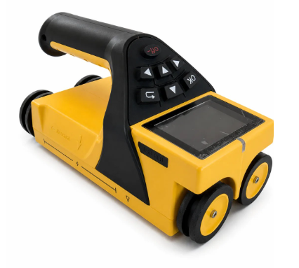
a) MIT Armotrek 1-1
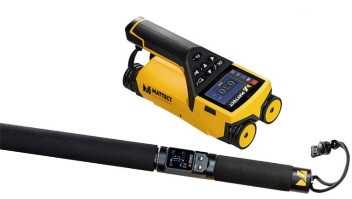
b) MIT Armotrek 2-1
Fig. 1. MIT Armotrek instrument range
Modern magnetic instruments for locating reinforcement, such as MIT ARMOTREK, generally do not require individual calibration relationships and operate on a “switch on and start working” principle. Reference measurements of diameter and cover thickness are taken in areas where the reinforcement has been directly exposed or on a special specimen solely to monitor the stability and reliability of the results obtained during work.
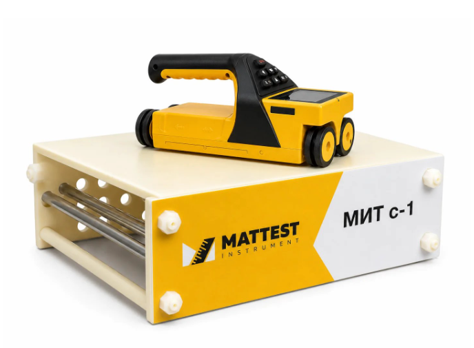
Fig. 2. MIT S-1 calibration specimen
The physics of the method is simple, but understanding it is important for determining and accounting for errors when working with any instrument based on magnetic measurement.
The method is based on the interaction of the instrument’s magnetic field with ferromagnetic reinforcement. Essentially, the instrument measures a change in the magnetic reluctance (inductance) of the medium.
There are four key physical aspects:
Nature of the field (low-frequency or static). The instruments generate an alternating (usually 5–100 kHz) or pulsed magnetic field. Concrete and air are “transparent” to it (magnetic permeability ≈ 1). Steel has a permeability 200–1000 times greater. The field lines are effectively “drawn into” the reinforcement, changing the inductance of the sensor coil. The closer the bar, the greater the change.
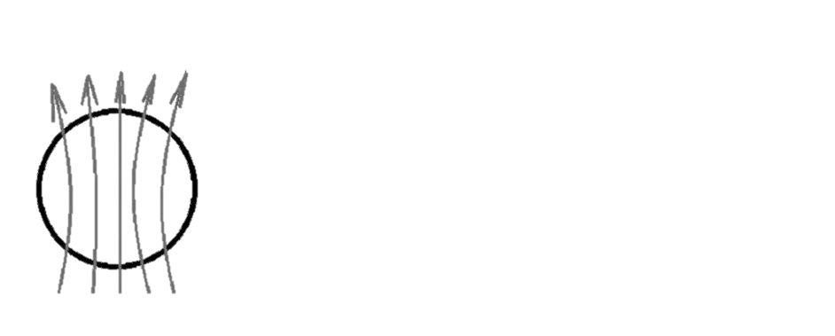
a) ferromagnetic material (K>1)

b) paramagnetic material (K=1)
Fig. 3. Magnetic materials
Exponential attenuation is the main enemy.
Field strength decreases in inverse proportion to the cube of distance (the dipole law). This means that a bar at a depth of 20 mm produces a signal eight times stronger than the same bar at a depth of 40 mm. The method is therefore accurate for small cover thicknesses (up to 60 mm), while at depths greater than 100 mm the error may rise sharply.
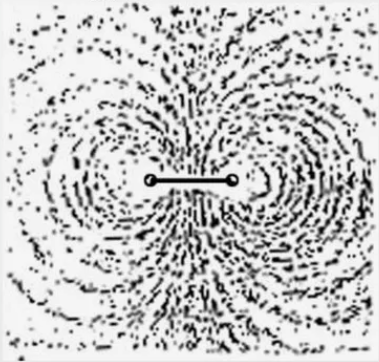
Fig. 4. Attenuation of the magnetic field
Influence of bar diameter (the “mass” effect).
The instrument measures a volumetric magnetic flux rather than a point. If the reinforcement diameter is greater than its embedment depth, the signal is at its maximum. If the diameter is smaller, the bar does not “capture” enough of the field. This is precisely why we cannot accurately measure cover without knowing the diameter: the same signal may correspond to Ø12 at a depth of 30 mm or Ø20 at a depth of 40 mm.
Edge effect and mesh spacing.
The magnetic field is not focused on a point: it covers a zone approximately 1.5–2 times the depth in diameter. If the distance between bars is smaller than this zone, their fields overlap (superposition). The instrument displays an averaged signal, making the reinforcement appear closer to the surface than it actually is.
Several other points should also be considered during work:
After welding and bending, and also during service, internal stresses accumulate in reinforcing steel. They “lock” the domains (microscopic regions with aligned magnetic moments), and residual magnetization occurs. Such bars produce a signal 30–50% stronger than a bar without stresses. Therefore, during an inspection it is not enough merely to check the instrument on a calibration specimen: a direct check on an exposed area of the structure being examined is also necessary.
For the magnetic method, tying wire and embedded metal parts are indistinguishable from reinforcement. If a heating cable with a metal braid lies beneath an underfloor heating mesh, the instrument will show “reinforcement” even though none is present there.
The instrument detects the maximum magnetic flux rather than the exact position of the bar. Because the field covers a zone 1.5 times the depth in width, the actual centre of the bar may be displaced by 5–10 mm from the signal peak. An experienced engineer always makes two passes, lengthwise and crosswise, to locate the true axis.
Having understood the main nuances of the physics behind the magnetic method of locating reinforcement, you can confidently begin working with the MIT Armotrek instrument. Using a modern instrument will provide the laboratory engineer with reliable test results.
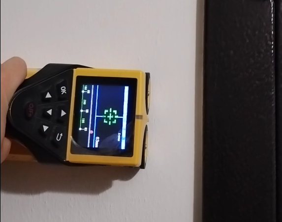
a) MIT Armotrek 1-1
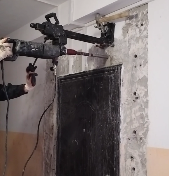
b) Drilling work
Fig. 5. MIT Armotrek 1-1 locating reinforcement before drilling work